Continue to Site

Welcome to EDAboard.com

Welcome to our site! EDAboard.com is an international Electronics Discussion Forum focused on EDA software, circuits, schematics, books, theory, papers, asic, pld, 8051, DSP, Network, RF, Analog Design, PCB, Service Manuals... and a whole lot more! To participate you need to register. Registration is free. Click here to register now.

Constant Current Source problem

Status
Not open for further replies.

garg29

Advanced Member level 1
Joined
Nov 17, 2004
Messages
443
Helped
25
Reputation
50
Reaction score
10
Trophy points
1,298
Activity points
3,593
constant current source

Hi friends,

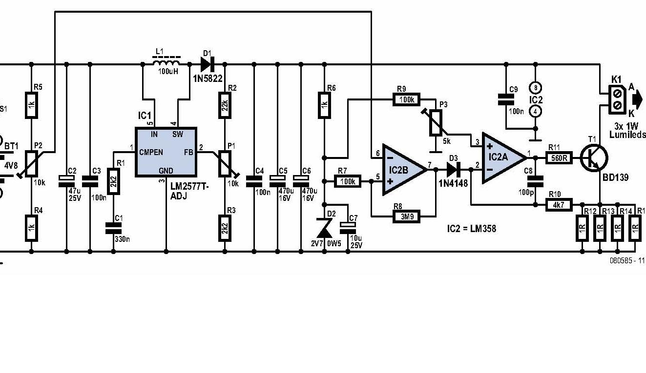
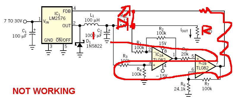
I have to design a project in which i have to generate constant current & this constant current should be variable through microcontroller, but before interfacing with microcontroller i'm trying to create a circuit for constant current source only. I'm trying to use LM2576 for the same. I found many circuits on net here also on eda but none of them is working. I'm using this constant current for some electrolysis process. when i use normal opamp-transsistor based circuit (as shown in the disgram) it works fine but there is Huge Heat dissipation due to this reason i want to shift to this regulator.


please see that attachments.


I'm unable to find the problem please help me.

Thanks.

With best regards.
 

current source

Hai

I am also looking for a solution for this implementation. Will keep in touch
Roy
 

    garg29

    Points: 2
    Helpful Answer Positive Rating
how to use constant current source

I have built LM2576 CC4.JPG long time ago and it worked fine. Make sure your connections and part values are right.
 

100ma current source

CMOS thanks for replying. do you remember what input voltage you feed. I tried increasing the input voltage, the results improved to some extent i.e upto 0.5A it got constant further it lost it's consistency.
 

constant current source scheme

You didn't mentioned which problems you observed in LM2576 based current regulator, I guess, instabilities? Also the load impedance should be known. The circuits can be most likely put to work with by modifying the loop compensation.
 

problems with current source

Hi Garg,

Transistor current source with opamp works fine i tested this ccurrent Source,
it works as per equation: i= (Vref/Rsense) Vref= Voltage at Non inverting Pin of opamp.

better what you can do is Implement a DAC and change Vref at that Pin and you can varry the current.

Even with this configuration heat problems are certain, because transitor is operating in active region,
one soultion is to put Vref as Common and use multiple transitors and opamp, i did the same way..


All the best.
--Babesh
 

current source lm2576

garg29 said:
CMOS thanks for replying. do you remember what input voltage you feed. I tried increasing the input voltage, the results improved to some extent i.e upto 0.5A it got constant further it lost it's consistency.
Input voltage was 24V and had a bank of 3 resistors (switched) for 350mA, 700mA and 1000mA load current. It was designed for driving HB white LEDs.
 

    garg29

    Points: 2
    Helpful Answer Positive Rating
current source problems

Thanks CMOS for replying again. Can you please send me your completed circuit diagram, i'll be really greatful to you.
 

lt1070 constant current

Hi garg29.
I think u should us MC34063 to make a constant current circuit. It's sense registor.
I (constant) = 0.33/R
 

current source problem

Hi Garg29

Did you try to simulate this circuit? I used Multisim (ex Workbench ) and program is really good.
 

lm2576 as constant current source

Dear Friend

look at this circuit i also moving topic to hobby circuit as this is not right forum for this kind of post

42_1246617779.jpg


Regards
Fragrance
 

why use a constant current source

garg29, the CCS design using lm2576 is overly complicated.

the two opamps act as an "error" amplifier and feed the error to the feedback pin of the lm2576.

fortunately, inside that feedback pin there is already an error amplifier.

the voltage drop at the feedback pin should be 1.35v (for the adj. version, and 3.3v/5v/12v/15v for their respective versions). so all you need is to pick a resistor R so that when the desired current goes through it, it will drop 1.35v/3.3v/5v....

let's say that you want 100ma current, and you have a lm2576-adj, the resistor R=1.35v/.1=13ohm, and power lose on it is .135w.

obviously, in your application, you will need to make sure that other specs aren't exceeded.

that topology is basically what you have in most of the LED driver ICs. some of them use step-up converters and others step-down converters (like this one).


Added after 2 minutes:

Fragrance, your design is basically a linear CCS, principlly identical to the first one the original poster tried.

ic2a is the error amplifier, and t1 is the regulator - it is always on -> high power dissipation and low efficiency. the smps is there to maintain a stable rail for the regulator.

Added after 32 minutes:

here is a slightly different example showing how a boost converter can be used to form a constant current source.

lt1070 has a feedback voltage of 1.25v. so to generate 100ma constant current, the resistor needs to be 12.5ohm.

the red trace in the simulation is the current going through the diode, and the green trace is the input voltage. those six diodes drop a total of 18v, plus the 1.25v on R2, the chip boosted the input (4-6v 100hz rectified ac) to a constant 19v dc.

you can use any boost / buck converter for this: th eprinciple is the same. you just need to rearrange the wiring slightly based on topology used.


constant current regulator

The opamp circuit should be working fine. I guess the heat dissipation is on the transistor? You may check if the transistor is properly biased and the voltage and current are at the levels they are supposed to be at.

Since it's a current source, it tries to maintain a current level when the load impedance is high. When it's high the voltage will go up and therefore the power consumption. Check if the load is too high.
______________________________________________________
low cost 1/4W resistor kit:
**broken link removed**
 

constant current source mos

boss i need to design a constant current source whose output should be 4ma(r.m.s),(sinusoidal excitation current) and frequency (20-100)khz need ur help in gettin ckt am asking u because ur working in the same field pls help me frnd....
 

need 100khz frequency and 4ma sinusoidal output

Check this scheme.
 

Status
Not open for further replies.

Part and Inventory Search

Welcome to EDABoard.com

Sponsor

Back
Top