Continue to Site

Welcome to EDAboard.com

Welcome to our site! EDAboard.com is an international Electronics Discussion Forum focused on EDA software, circuits, schematics, books, theory, papers, asic, pld, 8051, DSP, Network, RF, Analog Design, PCB, Service Manuals... and a whole lot more! To participate you need to register. Registration is free. Click here to register now.

Constant Current Boost Converter using LT1172

Status
Not open for further replies.

eanema

Member level 2
Joined
Sep 30, 2009
Messages
43
Helped
2
Reputation
4
Reaction score
2
Trophy points
1,288
Activity points
1,740
Hi All,

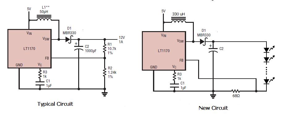
I'm trying to build a constant current boost converter to drive a chain of LEDs. I have picked an appropriate inductor, (over kill for the situation - 330 uH, 600 mA saturation current) I didn't realise that the output would be so dependent on the capacitance though. I hooked up the circuit as attached.

The LT1172 data sheet is here.

I choose the 68Ω resistor because I figured that the converter would do its best to set the output voltage to what ever it needs to be at to maintain the feed back voltage at 1.24v (see the block diagram in the data sheet) V=IR, 1.24v/20mA~=68 ohms. This seems to work, but is very dependent on the capacitor. I found that using an electrolytic 4.7uF cap rated at 60v worked best but the feed back voltage never reached 1.24v. The closest it got was ~1.1v and the worst (with other capacitors) was ~0.3v or 0v with no capacitor present. This means that I never reached the expected 18.2 mA, the closest I got was 16.2 mA.

Essentially, my question is this: how do I choose the correct capacitor.

Also, how important is the choice of diode? Could this be effecting my current problem?


No expert on SMPS design here, but I suspect you may be limiting yourself by selecting too high an inductance.

Note the comment under "Operation," in the data sheet. "...the switch is turned "on" at the start of each oscillator cycle. It is turned "off" when switch current reaches a predetermined level." Is it possible that the ramp up of switch current is too slow for the fixed internal timing of the device because your inductance is 6.6 times what they show in their sample circuits?

See what happens with a smaller inductance.

awright
 
  • Like
Reactions: eanema

    eanema

    Points: 2
    Helpful Answer Positive Rating
excellent, that worked very nicely. I had chosen the 330uH inductor using the inductor selector on the coil craft website. I guess i should have just trusted the data sheet.

Thanks

The question still remains though, how does one select a proper capacitor for a boost design? What I have works, but size is an issue, so I'd like to have the smallest cap necessary to operate.
 

It depends largely on the ripple you can afford to have on the output of the boost converter. For the LED driver (current controlled), it should not be a problem to allow a higher ripple.

The capacitor has mailnly two properties that influences the ripple voltage (current) at the output of the converter: capacitance value and ERS (equivalent series resistance). I think the last one is more critical for your application, because it can influence the stability of the control loop for the converter.
 
  • Like
Reactions: eanema

    eanema

    Points: 2
    Helpful Answer Positive Rating
Thank you all for your help. I have built the "new circuit" above with a 50 uH inductor and every thing is great. But in prototyping I managed to blow one of my switchers. It happened when I put too many diodes into the LED chain and the circuit attempted to create a voltage too high for the switcher to handle.

Next I got a board printed with three copies of this circuit sharing a common supply (think: red green and blue). After I soldered every ting together I tested each circuit in turn. The first one worked, then the second one, finally the third but when the third one was working, I noticed that the switcher and the inductor for the first two circuit had failed, with the switch open, shunting a lot of power through the inductor to ground.

I replaced the one of the switchers with a spare and every thing was fine again. I *think* that they failed because I operated them with an open circuit for a load. I'd like to prevent this and I'm thinking that a 75v zener in parallel with the LED chain would act as an ~infinite load until the output reaches 75v at which time it will prevent it from going any higher.

Does this sound reasonable?
Are there any other thoughts why this circuit might fail?
Any other possible methods to fix the problem... these switchers are about $10 a piece and I'd like my circuit to be fairly robust.

Thanks for any and all input to come
 

I'm trying to do almost the exact same thing with an LT1170 (TO-220 pkg). I'm trying to boost ~11V to ~13V to drive 4 LEDs in series at ~1.2A. I'm using a 1 Ohm power resistor where the OP has 68 Ohm. I've tried 47uF up to 1000uF as the output cap. Sometimes things stabilize (no audible noise and steady output on the Scope). However, sometimes it starts "squealing" and "squeaking" at around 1kHz (seen via scope at Vout). At this point the switcher starts making a lot of heat. I tried adding a small cap from Vout to the Fb pin. It seemed to help, but is unreliable.
I've tried 100uH and 27uH inductors. I don't have a 50 uH on hand. I have a 68uH on the way from CoilCraft.
Can someone lend some insight to what might be causing the instability.
 

This is just an off-the-cuff guess but I'm thinking your inductor might be saturating. What is its rated saturation current? (This is different from the rated current carrying capacity) Try watching the voltage across the inductor (VL=Ldi/dt)
 

This is just an off-the-cuff guess but I'm thinking your inductor might be saturating. What is its rated saturation current? (This is different from the rated current carrying capacity) Try watching the voltage across the inductor (VL=Ldi/dt)
I was still getting some "squealing" with the 100uH inductor but added a 100nF ceramic cap from feedback to ground. That seemed to settle things. Then I just came across a CoilCraft 68uH inductor. 2.7A RMS, 3.4A Sat, 0.044 Ohm. swapped that for the 100uH and things are running quite nicely now. Switcher is quiet and cool. Of course I am in a breadboard. Those things are never really great for testing switchers. I'm going to build a prototype board and see how things go.
I appreciate your feedback.
 

Status
Not open for further replies.

Similar threads

Part and Inventory Search

Welcome to EDABoard.com

Sponsor

Back
Top