Continue to Site

Welcome to EDAboard.com

Welcome to our site! EDAboard.com is an international Electronics Discussion Forum focused on EDA software, circuits, schematics, books, theory, papers, asic, pld, 8051, DSP, Network, RF, Analog Design, PCB, Service Manuals... and a whole lot more! To participate you need to register. Registration is free. Click here to register now.

Connecting LED's in parallel

Status
Not open for further replies.

pekry416

Newbie level 3
Joined
Jan 13, 2011
Messages
3
Helped
0
Reputation
0
Reaction score
0
Trophy points
1,281
Activity points
1,318
Hi Guys,

I understand that if you connect led's in parallel, the voltage will be the same across all 3 leds?

In multisim I've connected 3 led's in parallel, using LT1761ES5-3 as the regulator to step the voltage down to 3v, and it works perfectly for one led, the voltage is 3v, and when I alternate the circuit Vin between 6 and 13v the voltage to the led remains at 3v, perfect!

However when i add the 2nd led the voltage drops to 2.8v, and then when i add the 3rd led the voltage drops to 2v. Also with these aditional led's when i alternate the circuit Vin the voltage across the leds is also alternating.

Iv attatched a print screen of my circuit. Please could somebody shed some light on the situation as to why the voltage is dropping as im really confused?

Many thanks.
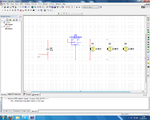
led.png
 

Measuring the current would help, you are pulling 2 and 3 times more current compared to the circuit with one led and since you have no resistors i assume that this current is high.
Measure the current in each led node and also the total current that the regulator has to give.

Alex
 

Those aren't LEDs that would draw <100 mA total, they're light bulbs that will draw far more than the 100 mA the regulator is designed to provide. In addition to that, you have no output bypass capacitor. These simulators are great but they should also have an animation showing the regulator blowing up and smoking.

LEDs are current dependent devices. If you insist on using a voltage regulator to drive them, then I recommend using an adjustable model in a current regulating mode. The LM317L was suggested to you on your other thread. I've used this method and it works well.

https://www.national.com/ds/LM/LM317L.pdf

https://www.fairchildsemi.com/ds/LM%2FLM317L.pdf

https://www.st.com/stonline/products/...168/lm317l.pdf

https://www.onsemi.com/pub_link/Collateral/LM317L-D.PDF

https://www.utc-ic.com/spec/LM317L.pdf
 
Last edited:

Yes these are bulbs, you are right, but i don't agree with "LEDs would draw <100 mA total",
even one green led rated at 2.2v can draw more than 200ma if you don't use a resistor with the 3v power supply .

Alex
 

I'm assuming a non-destructive circuit design. Unfortunately, multisim will show an LED happily glowing at a current level that will destroy it. The OP previously posted his LED specifications and they were rated at 30mA.
 

The OP previously posted his LED specifications and they were rated at 30mA.
Funny!
So we should better revert to the general accepted LED circuit design rules:
- operate LEDS current controlled or with a current limiting resistor
- don't connect LED's in parallel without individual current limiting resistor

In special cases, when same type LEDs are mounted on a common heatsink or are operated at low currents, so that thermal runaway can't occur, parallel circuit may be an option, according to the manufacturer specifications. But a current regulation means is required anyway.
 

If you connect LED's in parallel the current consumption is more and voltage applies to all are same,

so you can connect the leds in parallel but have to connect with sufficient current support source,

regards
Sreekanth
 

Status
Not open for further replies.

Similar threads

Part and Inventory Search

Welcome to EDABoard.com

Sponsor

Back
Top