Continue to Site

Welcome to EDAboard.com

Welcome to our site! EDAboard.com is an international Electronics Discussion Forum focused on EDA software, circuits, schematics, books, theory, papers, asic, pld, 8051, DSP, Network, RF, Analog Design, PCB, Service Manuals... and a whole lot more! To participate you need to register. Registration is free. Click here to register now.

components value in given diagram

Status
Not open for further replies.

rajaram04

Advanced Member level 3
Joined
Jun 17, 2012
Messages
871
Helped
6
Reputation
12
Reaction score
5
Trophy points
1,298
Location
earth
Visit site
Activity points
7,687
Hello sir

I found a link explaning a T flip flop using transistors with the circuit diagram shown below with link

https://electriciantraining.tpub.com/14181/css/14181_124.htm

14181_124_2.jpg

please tell me here . . is the circuit ok ???????

What are the components value i should apply could you please explain ?

i am too having doubt on transistor type cause it is using pnp one & we all know about bi-stable design well
 
Last edited:

This looks like a bistable multivibrator. You have more than one input to make it change state.

The toggle input might be tricky to make it work right. The circuit needs to be adjusted carefully, so it can be toggled to the opposite state by a toggle pulse, whether it is presently in the Off or On state.

Component values are similar to the classic astable multivibrator. I think R3-4 are several thousand. R5-6 are several hundred.

I'm not sure about R1-2. These provide enough bias current to make the transistors hold their state. But that current must not be so great that it cannot be overcome by the toggle pulse.

The capacitors can be sufficiently large to slow down the action so our eyes can follow.

If you wish, you can replace the PNP's with NPN's, and reverse the diode directions, and reverse the supply polarity.


Sir which capacitor you are talking about ? C3-4 ?????

So would you tell any of approx value ??

are these of ceramic or electrolytic type ???

And what about C1-2 value ??

What about diode ? i mean IN4147 is okk for that ?

- - - Updated - - -

one more circuit i found while googling . . Is it okk ? What should be the value of C1-2 ????????????

0173.GIF
 

Sir which capacitor you are talking about ? C3-4 ?????

So would you tell any of approx value ??

are these of ceramic or electrolytic type ???

And what about C1-2 value ??

What about diode ? i mean IN4147 is okk for that ?

The answers depend on what speed you're operating at. Fast speeds go with small capacitor values, and fast recovery diodes.

If the capacitor charge is first positive, then negative...
then you cannot use an electrolytic.

Try what I do. Start at 1uF. Experiment with circuit operation, see how fast the capacitor charges and discharges. If it seems 'too slow', reduce the Farad value. Etc.

one more circuit i found while googling . . Is it okk ? What should be the value of C1-2 ????????????

View attachment 90580

This is from the Navy Electricity and Electronics Training Series.
Module 9—Introduction to Wave-Generation and Wave-Shaping.
Page 117. Figure 3-17A.

www.hnsa.org/doc/neets/mod09.pdf

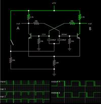
Although the text has an explanation, the schematic omits the toggle switching method.

To develop a working circuit, I made a simulation:


The capacitor values are chosen so they charge and discharge at what seems like a 'reasonable' rate.

Notice the transitions are not clean.

Operation is not always reliable. A toggle event needs to charge/discharge the capacitors, or else it puts the circuit in an unstable condition. As though it needs a moment to 'make up its mind' whether the left-hand transistor should conduct, or the right-hand.
 

The answers depend on what speed you're operating at. Fast speeds go with small capacitor values, and fast recovery diodes.

If the capacitor charge is first positive, then negative...
then you cannot use an electrolytic.

Try what I do. Start at 1uF. Experiment with circuit operation, see how fast the capacitor charges and discharges. If it seems 'too slow', reduce the Farad value. Etc.


This is from the Navy Electricity and Electronics Training Series.
Module 9—Introduction to Wave-Generation and Wave-Shaping.
Page 117. Figure 3-17A.

www.hnsa.org/doc/neets/mod09.pdf

Although the text has an explanation, the schematic omits the toggle switching method.

To develop a working circuit, I made a simulation:


The capacitor values are chosen so they charge and discharge at what seems like a 'reasonable' rate.

Notice the transitions are not clean.

Operation is not always reliable. A toggle event needs to charge/discharge the capacitors, or else it puts the circuit in an unstable condition. As though it needs a moment to 'make up its mind' whether the left-hand transistor should conduct, or the right-hand.


hmm sir as per instruction i did but its not working like a bi-srable
when i make it trigger & hold the state changes & when i release the state returns back to original or previous condition :roll:

what to do now ?
 

hmm sir as per instruction i did but its not working like a bi-srable
when i make it trigger & hold the state changes & when i release the state returns back to original or previous condition :roll:

what to do now ?

Right, it is not always reliable. This makes it difficult to use.
It's no surprise that that schematic only appears in a few places. We seldom see projects which use it.

Also notice the schematic is incomplete. It does not show the characteristics of the toggle pulse. It is up to the reader to find out. I had to try several resistor and switch arrangements, before I found out what the 'toggle' pulse needs to be like.

To make the operation more reliable, it might help to experiment, to find values which provide reliable operation. To create a more definite (or perhaps wider) range of action on the capacitors. Etc.
 

Yo yo yo
here we go
I made some changes & circuit is working very properly
a diode is connected in between base and triggering condencers
a 220 k resistor from collector to the corresponding diode condencer junction is connected & same has to be connected in other side also
emmiter is directly connected to the ground point
thats it
:lol:
 

Status
Not open for further replies.

Part and Inventory Search

Welcome to EDABoard.com

Sponsor

Back
Top