Vermes
Advanced Member level 4

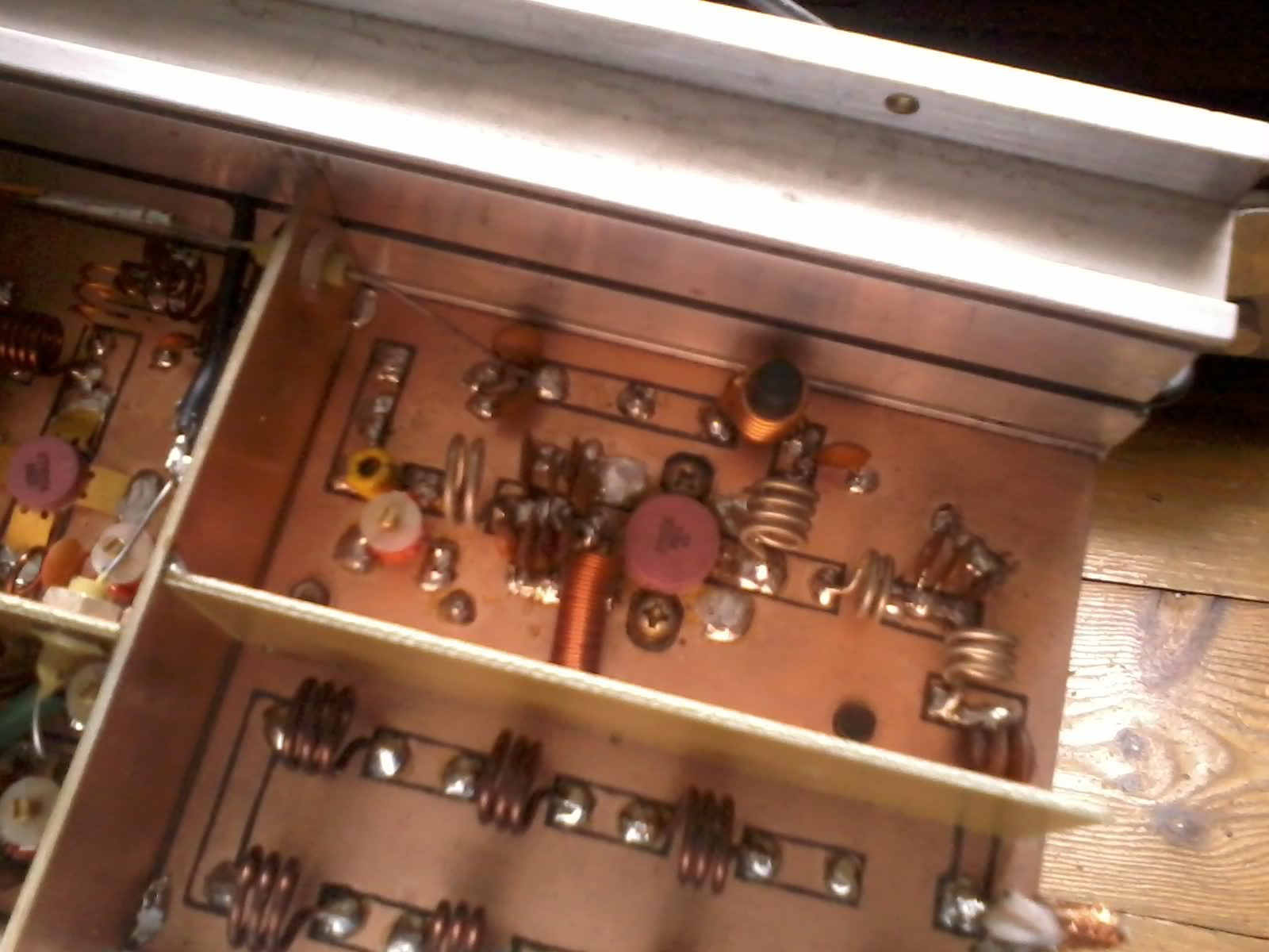
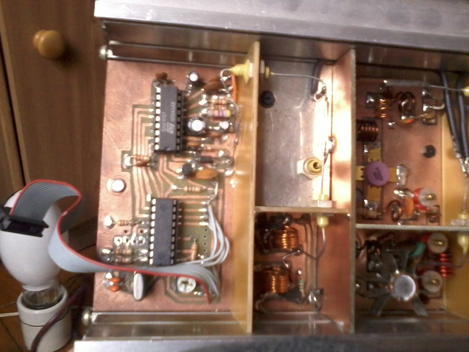
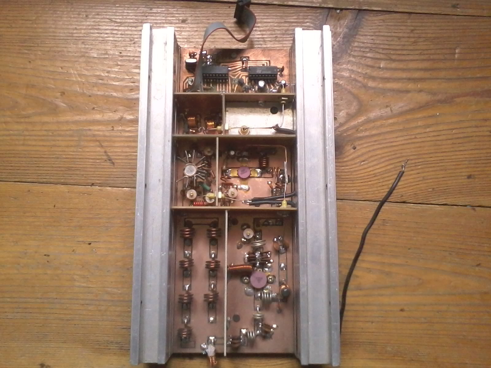
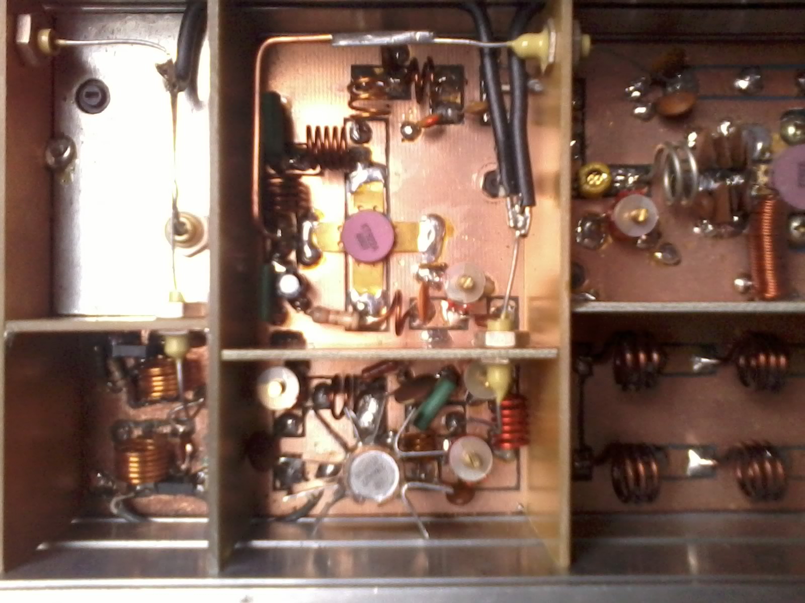
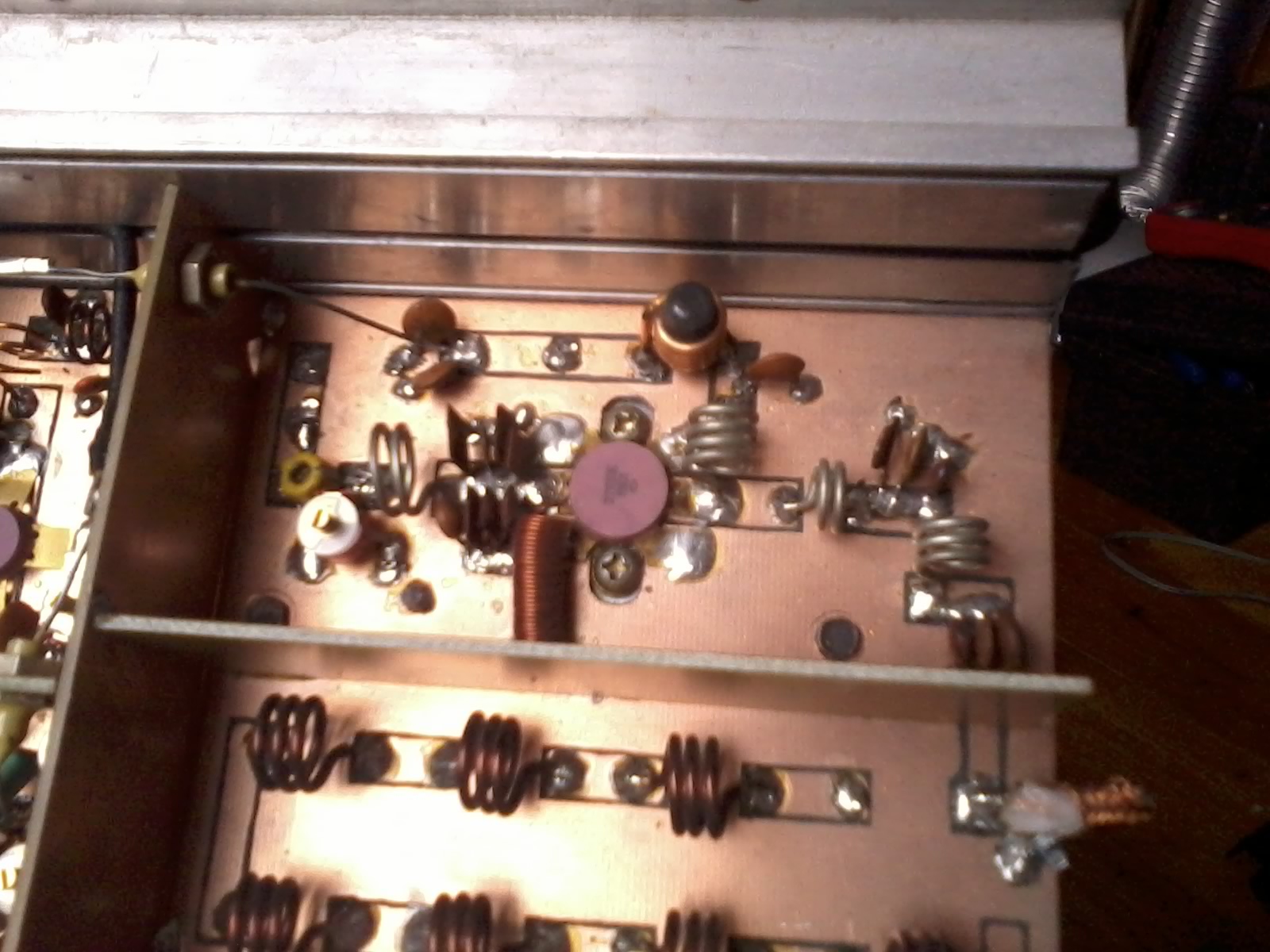
The transmitter is closed in a housing which is the hest sink for the final transistor. The housing contains the individual modules (each board was made separately):
- Seiler generator on BF199 (+ separator on BF199), warikap is easily available BB104. 12V power supply. It is very stable, even without synthesis, but the outgoing power is very small.
- PLL synthesis – a typical synthesis on SAA1054 and PIC16F84A with a LCD display. Frequency is adjustable (depending on the load) between 87,5-108MHz. Turning on the loop is indicated by the word „LOCK”.
- control steps. Two on BF194, one on 2N4427 and the last one on KT922A. All except KT are on 12V. You can gain 3-5W from the last control step at 24V.
- power amplifier – transistor 2T930b. 5W on the input, 24V and 80W output power. You can gain 110W from it, but it is a pointless treatment. Much more heat and power attemperated.
Pictures:
Link to original thread (useful attachment) – Kompletny nadajnik UKF 80W (synteza PLL)