nomad13
Full Member level 3
compim
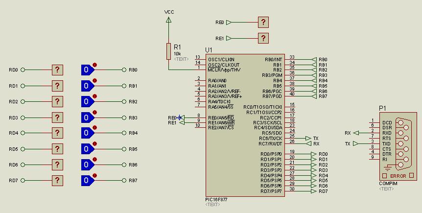
I tried to use compim feature of proteus to communicate to a GSM module. I use a 16F877 pic, the tx and rx are directly connected to a compim.
I send data to a compim but I receive unknown data on the other end.
What do I need to do?
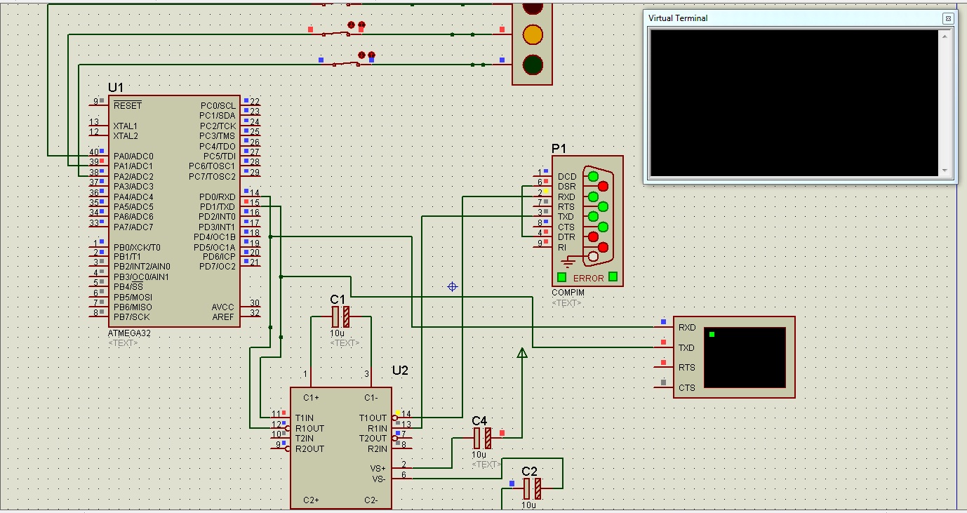
I tried to use max232 on the circuit but I don't recieve any on the reciever end.
Can someone attach a board layout using a pic and a compim in proteus.
Thanks
I tried to use compim feature of proteus to communicate to a GSM module. I use a 16F877 pic, the tx and rx are directly connected to a compim.
I send data to a compim but I receive unknown data on the other end.
What do I need to do?
I tried to use max232 on the circuit but I don't recieve any on the reciever end.
Can someone attach a board layout using a pic and a compim in proteus.
Thanks