Continue to Site

Welcome to EDAboard.com

Welcome to our site! EDAboard.com is an international Electronics Discussion Forum focused on EDA software, circuits, schematics, books, theory, papers, asic, pld, 8051, DSP, Network, RF, Analog Design, PCB, Service Manuals... and a whole lot more! To participate you need to register. Registration is free. Click here to register now.

[SOLVED] Comparing Square wave with a fixed reference voltage

Status
Not open for further replies.

abuhafss

Full Member level 2
Joined
Aug 8, 2010
Messages
136
Helped
1
Reputation
2
Reaction score
0
Trophy points
1,296
Activity points
2,346
Hi

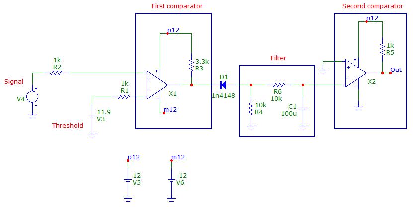
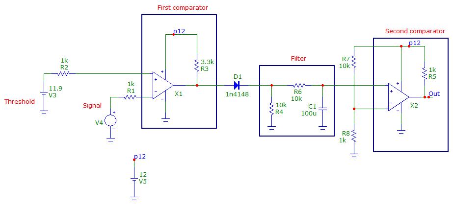
I need to compare a square wave signal with a reference voltage (11.90v).

In condition A, the sq. wave fluctuates between 11.89 and 12.00v which means the reference voltage falls within the range of the square wave.

In condition B, the sq. wave fluctuates between 11.95 and 12.00v which means the reference voltage is below the range of square wave.

I want to compare in such a way that I get 12v at the output of the comparator LM393 for condition A and 0v for condition B.

The supply voltage is 12v and the frequency of the sq. wave is about 1.4Hz.

Thanks in advance for the help.
 

Attachments

  • Sq Wave Signal.gif
    Sq Wave Signal.gif
    27.1 KB · Views: 89

Do you care if the square-wave goes above 12V or just that it is above 11.9V?

It cannot go above 12v.
Condition A, lower limit is 11.88v and maximum 12v
Condition B, lower limit is 11.95v and maximum 12v
 

I think you can use the following circuit:


A first comparator subtract the threshold from the signal, then only if the signal goes below the threshold a negative voltage will be generated. Then after the diode we'll have zero if the signal is always higher that the threshold, otherwise we'll have a negative squarewave. Then filtering the squarewave and applying a 2nd inverting comparator (single supplied to avoid negative voltages) we should have the requested behaviour.
However, in practice, you have very small difference between signal and threshold, then the noise could play a major role. Probably a pre-conditioning and light filtering of the signal could be required as well as some hystheresis (high value resistor from out to non-inverting input) on the first comparator

Thanks for your help, it worked. However, I have size restriction with my project.

1) I can use a single 8-DIP (dual op amp) which has common Vcc and GND. How can I provide (-)ve supply for only one comparator?

2) My power supply has to be single 12v supply. I cannot include a supply splitting circuit to make (-)ve supply available.
 

I modified the circuit so you can use two comparators supplied by +12V only. I exchanged inverting and non-inverting input of the first comparator, so at its output you will have zero or a positive squarewave. Then also the diode has to be reversed.
The second comparator has to be reversed and needs now a small voltage on the invertiong input.


Please try if it works.


Thanks once again. Yes, now it is perfect!
And bundle of thanks for the explaining both the schematics.
 

Status
Not open for further replies.

Similar threads

Part and Inventory Search

Welcome to EDABoard.com

Sponsor

Back
Top