Continue to Site

Welcome to EDAboard.com

Welcome to our site! EDAboard.com is an international Electronics Discussion Forum focused on EDA software, circuits, schematics, books, theory, papers, asic, pld, 8051, DSP, Network, RF, Analog Design, PCB, Service Manuals... and a whole lot more! To participate you need to register. Registration is free. Click here to register now.

Comparator hysteresis with cross coupled PMOS devices

Status
Not open for further replies.

student153

Member level 1
Joined
Jun 16, 2006
Messages
38
Helped
1
Reputation
2
Reaction score
1
Trophy points
1,288
Activity points
1,524
Comparator design

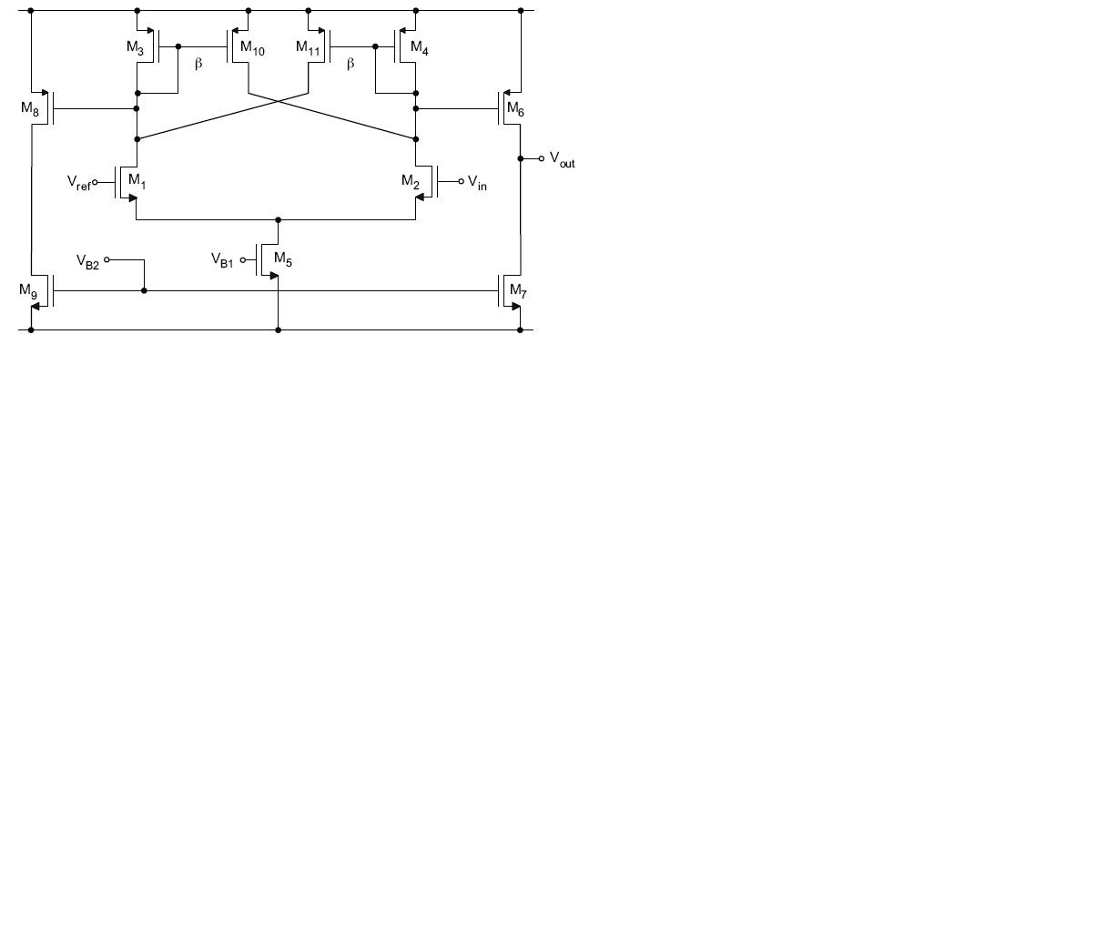
I am designing hysteresis comparator (see the attached schematic). I am facing a strange issue. Even when i make the cross coupled PMOS devices (M10, M11) equal in size to the diode connected load (M3, M4), i still get 13 mV of hysteresis and even if i reduce the size of M10, M11 than M3, M4 still i get 7-8mV of hysteresis. Does anybody have an idea whats going on here.
 

Comparator design

That's right! The comparator will have hysteresis unless you remove the cross coupled devices.
 

Re: Comparator design

rfcn said:
That's right! The comparator will have hysteresis unless you remove the cross coupled devices.
Cross coupled devices have negative resistance viz -1/2gm and if they have the same size as diode connected devices then it means total resistance will be zero and no positive feedback will be there. Also if you look into Allen Holberg page no. 471 he says " If positive feedback is less then negative feedback then no hysteresis will result " Also in the same paragraph he says that "As long as ratio β6/β3 is less than 1 there is no hysteresis" (he defines β as µCoxW/L, while subscripts 6 and 3 refer to his picture number 8.4-11
 

Re: Comparator design

rfcn said:
That's right! The comparator will have hysteresis unless you remove the cross coupled devices.
Anybody please!!
 

Re: Comparator design

Hi,

I've faced the same issue once. The problem was not in the circuit, but in the step size of DC sweep: automatic value was too large. 1e-3 linear step solved the issue.
 

    student153

    Points: 2
    Helpful Answer Positive Rating
Re: Comparator design

Hi dedalus,

let me clear what you say. If we make the cross coupled devices the same size as diode connected load then we should not see any hysteresis provided we set the DC sweep interval very small like 1e-3. right?
I also observed another thing that if we make our cross coupled devices smaller than diode connected ones then in the transient simulation comparator works perfectly and its response time improves as we reduce further and further the size of cross coupled as compared to diode connected devices. Do you see it is possible or it is also again due to less resolution of transient simulations. I wanna reduce the response time, is there other things i can try. I have already pushed input diff pair to their limit.
 

Re: Comparator design

which simulation did u try?
I think you should do a DC sweep instead of transient simulation. the hysteresis you observe may be just because of comparator delay
 

    student153

    Points: 2
    Helpful Answer Positive Rating
Re: Comparator design

liusupeng said:
which simulation did u try?
I think you should do a DC sweep instead of transient simulation. the hysteresis you observe may be just because of comparator delay
Thank you liusupeng, i got it.
 

Re: Comparator design

student153 said:
let me clear what you say. If we make the cross coupled devices the same size as diode connected load then we should not see any hysteresis provided we set the DC sweep interval very small like 1e-3. right?

If you perform DC simulation of any comparator without hysteresis, you can get false hysteresis due to the large step.

student153 said:
... also again due to less resolution of transient simulations.

Step in transient analysis usually varies during simulation: when signals doesn't change the step may be large, while when signal changes step may be very small to precisely track all changes. I don't think you can get some false results due to the "resolution" of transient analysis.


I thought you measured hysteresis in DC analysis, not in transient.
 

Status
Not open for further replies.

Part and Inventory Search

Welcome to EDABoard.com

Sponsor

Back
Top