Continue to Site

Welcome to EDAboard.com

Welcome to our site! EDAboard.com is an international Electronics Discussion Forum focused on EDA software, circuits, schematics, books, theory, papers, asic, pld, 8051, DSP, Network, RF, Analog Design, PCB, Service Manuals... and a whole lot more! To participate you need to register. Registration is free. Click here to register now.

[SOLVED] COMPARATOR for relaxation oscillator

Status
Not open for further replies.

cmos_ajay

Full Member level 2
Joined
Jan 30, 2007
Messages
126
Helped
0
Reputation
0
Reaction score
0
Trophy points
1,296
Activity points
2,247
Hello, I need a suitable comparator architecture in standard CMOS process for a relaxation oscillator. This oscillator has 2 comparators and 2 caps. Frequency = 20 Meg and VCC supply = 5V.

Basically a high speed low propagation delay comparator circuit is needed to get good linearity. Can some suggest papers that might prove helpful ?
 

A relaxation oscillator "comparator" could be as simple as
common-source NMOS (bottom) and PMOS (top) with
current source loads followed by inverters. If you are
not especially concerned with process variation.

Relaxation oscillators at higher frequencies, run up against
the limited discharge current (itself a very variable thing).
A symmetric triangle wave oscillator relieves this issue by
using (say) 2X up and 2X down currents (steered /
switched) rather than (say) 1X up, 100X down (to get
discharge dwell and its variability, minimized). 20MHz in
a 5V CMOS is getting up there for controlled-current
analog circuitry - I'd bet your cell library craps out below
200MHz and that's hard driven. So you need to look for
topologies that make it easy on the transistors.

I have to wonder just how important "linearity" (I presume,
f vs Ictrl) really is - a controlled oscillator usually being
part of a feedback system and control nonlinearity maybe
easily overcome by the loop gain? Be sure you understand
whether this is really a prime attribute, because it will tax
you quite a bit to achieve it (time, transistor count).
 

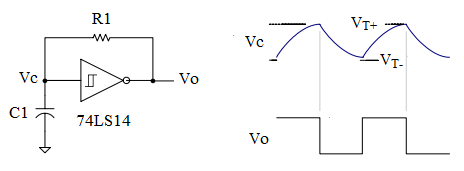
RC rise time is fairly linear over 1/3 Vpp so using an RC filter with hysteresis and negative feedback is the simplest.

The hysteresis levels are determined by the input threshold, normally Vcc/2 for CMOS and the output swing and the R ratio for positive feedback. Essentially design a Schmitt trigger with tight tolerances with Vcc/2 threshold and 10~25% hysteresis and 1% R &C values

Or use an off the shelf one (74HC14, etc. with wide tolerances using 1/3 to 2/3 thresholds and a pot to tune.
schmitt-trigger-osc.png
 

Hi dick_freebird, Thanks for the reply you gave . It was a detailed one. Do you have names of technical documents or papers where I can see the ideas you mentioned especially of the common-source used as comparator ?
 

... technical documents or papers where I can see the ideas you mentioned especially of the common-source used as comparator ?

E.g. something like this one: self-biased_comp.png
 

Status
Not open for further replies.

Part and Inventory Search

Welcome to EDABoard.com

Sponsor

Back
Top