subspace
Newbie level 5
Hi,
I am working on a project of interfacing PIC uP (MASTER) to Multiple PIC uP (SLAVES) through the use of half-duplex RS-485 chips.
I am using daisy chain topology for my network.
Hardware configurations:
-----------------------------
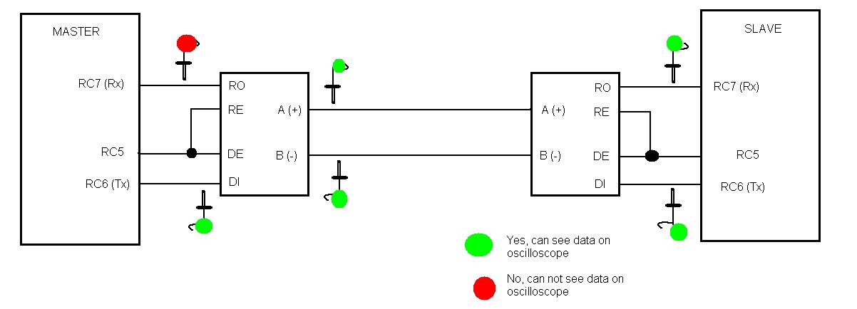
all of the RS-485 chips are connected as follow to the PIC uP:
RS-485 pin PIC16F876
------------- -------------
RO RC7(RX)
RE' RC5
DE RC5
DI RC6(TX)
120ohm termination resistor on the Master side
Software Configurations:
-----------------------------
Compiler: HT-PIC C
I am using rs232 subroutines, except that before I call my subroutine, I switch on and off RC5 accordingly to what ever operation I am currently trying to implement.
that is if I am trying to transmit, I set RC5 to 1 and then I call putchar() subroutine. then once I have finished transmitting I set RC5 to 0 before I call getchar() subroutine.
The following is the software code:
====================================
1: /*==========================================================================*/
2: /* Send 8-bit char using USART and Interrupt handler */
3: /*--------------------------------------------------------------------------*/
4: void putchar (unsigned char data_out)
5: {
6: serial_time = 10; // format timeout value for serial comm
7:
8: while (!TXIF && serial_time) // Wait until transmit reg empty using interrupt flag: TXIF
9: {
10: line_error();
11: }
12:
13: TXREG = data_out; // Write to Transmiter register
14:
15: return; // Resume PIC normal operation
16: }
17:
18: /*==========================================================================*/
19: /* receive 8-bit char using USART and Interrupt handler */
20: /*--------------------------------------------------------------------------*/
21: bit getchar(unsigned char *data_in)
22: {
23: serial_time = 10; // format timeout value for serial comm
24:
25: while (!RCIF && serial_time) // Wait until character is received using Interrupt flag: RCIF
26: { // Loops until user send info.
27:
28: line_error();
29: }
30:
31: if (!serial_time)
32: {
33: return (FALSE);
34: }
35:
36: *data_in = RCREG; // assign incoming data to DATA_IN.
37:
38: return(TRUE); // Resume PIC normal operation
39: }
40:
41: //==============------------- MAIN PROGRAM ---------------==================
42:
43: /*========================================================================*/
44: /* The Main Program */
45: /*------------------------------------------------------------------------*/
46: main(void)
47: {
48: unsigned char bydata; // counter variable
49: unsigned char sData[3]; // outgoing buffer from MASTER to SLAVES
50: unsigned char sData2[3]; // incoming buffer from SLAVES to MASTER
51:
52:
53: InitProc(); // Initialize uP and registery
54: serial_init(31,1); // Init. serial port
55:
56: sData[0] = 0x01; // SLAVE device address
57: sData[1] = 0x0C; // Poll command
58: crcValue = 0xFF; // initialize crcValue;
59:
60: sData2[0] = 0x00; // Clear Incoming buffer.
61: sData2[1] = 0x00;
62: sData2[2] = 0x00;
63:
64:
65: while(1)
66: {
67: bydata = 0x00; // reset counter
68:
69: RS_485_crc_CALC(sData, 3); // Calculate crcValue
70:
71: sData[2] = (255 - crcValue); // append crc value to outgoing buffer
72:
73: crcValue = 0xFF; // Reset crcValue
74:
75: // Prepare the MAster to transmit data to slaves
76: //-----------------------------------------------
77: RC5 = 1; // enable RS-485 driver (transmitter)
78: TXEN = 1; // enable transmitter
79: CREN = 0; // disable receiver
80:
81: for (bydata = 0; bydata < 3 ; bydata++)
82: {
83: putchar(sData[bydata]); // Send out the data to slaves
84: }
85:
86: // Prepare the master to receive data from slave
87: //------------------------------------------------
88: TXEN = 0; // Disable Transmitter
89: CREN = 1; // Enable Receiver
90: RC5 = 0; // Enable RS-485 Receiver
91:
92: for (bydata = 0; bydata < 3; bydata++)
93: {
94: getchar(&sData2[bydata]); // receive incoming data from slaves
95: }
96:
97: // Heart Beat Indicator :: inidicate that the pic has reached the end of code cycle.
98: if (!LEDTime) // Check Countdown
99: {
100: RA4 = (RA4 == FALSE);
101: LEDTime = TIMER1_LED_DELAY; // Restart
102: }
103:
104: CLRWDT();
105:
106: }
107:
108: }
109:
The above code does not work.
But if you insert the following lines:
for(i=0; i<95; i++); between lines :: 83 and 84.
for(i=0; i<5000; i++); between lines :: 103 and 104.
The slave successfully receives the poll command, but still the MASTER can not receive the response back from the slave.
IS THIS A SOFTWARE ISSUE?
IS THIS A TIMING ISSUE?
I am working on a project of interfacing PIC uP (MASTER) to Multiple PIC uP (SLAVES) through the use of half-duplex RS-485 chips.
I am using daisy chain topology for my network.
Hardware configurations:
-----------------------------
all of the RS-485 chips are connected as follow to the PIC uP:
RS-485 pin PIC16F876
------------- -------------
RO RC7(RX)
RE' RC5
DE RC5
DI RC6(TX)
120ohm termination resistor on the Master side
Software Configurations:
-----------------------------
Compiler: HT-PIC C
I am using rs232 subroutines, except that before I call my subroutine, I switch on and off RC5 accordingly to what ever operation I am currently trying to implement.
that is if I am trying to transmit, I set RC5 to 1 and then I call putchar() subroutine. then once I have finished transmitting I set RC5 to 0 before I call getchar() subroutine.
The following is the software code:
====================================
1: /*==========================================================================*/
2: /* Send 8-bit char using USART and Interrupt handler */
3: /*--------------------------------------------------------------------------*/
4: void putchar (unsigned char data_out)
5: {
6: serial_time = 10; // format timeout value for serial comm
7:
8: while (!TXIF && serial_time) // Wait until transmit reg empty using interrupt flag: TXIF
9: {
10: line_error();
11: }
12:
13: TXREG = data_out; // Write to Transmiter register
14:
15: return; // Resume PIC normal operation
16: }
17:
18: /*==========================================================================*/
19: /* receive 8-bit char using USART and Interrupt handler */
20: /*--------------------------------------------------------------------------*/
21: bit getchar(unsigned char *data_in)
22: {
23: serial_time = 10; // format timeout value for serial comm
24:
25: while (!RCIF && serial_time) // Wait until character is received using Interrupt flag: RCIF
26: { // Loops until user send info.
27:
28: line_error();
29: }
30:
31: if (!serial_time)
32: {
33: return (FALSE);
34: }
35:
36: *data_in = RCREG; // assign incoming data to DATA_IN.
37:
38: return(TRUE); // Resume PIC normal operation
39: }
40:
41: //==============------------- MAIN PROGRAM ---------------==================
42:
43: /*========================================================================*/
44: /* The Main Program */
45: /*------------------------------------------------------------------------*/
46: main(void)
47: {
48: unsigned char bydata; // counter variable
49: unsigned char sData[3]; // outgoing buffer from MASTER to SLAVES
50: unsigned char sData2[3]; // incoming buffer from SLAVES to MASTER
51:
52:
53: InitProc(); // Initialize uP and registery
54: serial_init(31,1); // Init. serial port
55:
56: sData[0] = 0x01; // SLAVE device address
57: sData[1] = 0x0C; // Poll command
58: crcValue = 0xFF; // initialize crcValue;
59:
60: sData2[0] = 0x00; // Clear Incoming buffer.
61: sData2[1] = 0x00;
62: sData2[2] = 0x00;
63:
64:
65: while(1)
66: {
67: bydata = 0x00; // reset counter
68:
69: RS_485_crc_CALC(sData, 3); // Calculate crcValue
70:
71: sData[2] = (255 - crcValue); // append crc value to outgoing buffer
72:
73: crcValue = 0xFF; // Reset crcValue
74:
75: // Prepare the MAster to transmit data to slaves
76: //-----------------------------------------------
77: RC5 = 1; // enable RS-485 driver (transmitter)
78: TXEN = 1; // enable transmitter
79: CREN = 0; // disable receiver
80:
81: for (bydata = 0; bydata < 3 ; bydata++)
82: {
83: putchar(sData[bydata]); // Send out the data to slaves
84: }
85:
86: // Prepare the master to receive data from slave
87: //------------------------------------------------
88: TXEN = 0; // Disable Transmitter
89: CREN = 1; // Enable Receiver
90: RC5 = 0; // Enable RS-485 Receiver
91:
92: for (bydata = 0; bydata < 3; bydata++)
93: {
94: getchar(&sData2[bydata]); // receive incoming data from slaves
95: }
96:
97: // Heart Beat Indicator :: inidicate that the pic has reached the end of code cycle.
98: if (!LEDTime) // Check Countdown
99: {
100: RA4 = (RA4 == FALSE);
101: LEDTime = TIMER1_LED_DELAY; // Restart
102: }
103:
104: CLRWDT();
105:
106: }
107:
108: }
109:
The above code does not work.
But if you insert the following lines:
for(i=0; i<95; i++); between lines :: 83 and 84.
for(i=0; i<5000; i++); between lines :: 103 and 104.
The slave successfully receives the poll command, but still the MASTER can not receive the response back from the slave.
IS THIS A SOFTWARE ISSUE?
IS THIS A TIMING ISSUE?