mshh
Full Member level 6
common ground problem
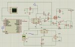
I have a problem with my circuit , i control buck converter using atmega8 and data acquisition card . my circuit has also LM35 temperature sensor .in the beginning i used one power supply to give +12 v and +5 v using lm7805 and that makes the regulator got hot , the problem is coming up when i connected all the ground to just one point . the control and power circuit have the same ground and that increased the output of lm35 however it should be lower . when i disconnect the power circuit the output of lm35 is gonna to be alright . then i tried to use power supply for the lm35 and another power supply for the power circuit but in a vain . lm35 is just connected to capacitor and resistor that is existed in its datasheet for filtration then a voltage follower op amp. i display PWM using oscilloscope (terminal and its ground)i attached the power and control circuit .so please help.
I have a problem with my circuit , i control buck converter using atmega8 and data acquisition card . my circuit has also LM35 temperature sensor .in the beginning i used one power supply to give +12 v and +5 v using lm7805 and that makes the regulator got hot , the problem is coming up when i connected all the ground to just one point . the control and power circuit have the same ground and that increased the output of lm35 however it should be lower . when i disconnect the power circuit the output of lm35 is gonna to be alright . then i tried to use power supply for the lm35 and another power supply for the power circuit but in a vain . lm35 is just connected to capacitor and resistor that is existed in its datasheet for filtration then a voltage follower op amp. i display PWM using oscilloscope (terminal and its ground)i attached the power and control circuit .so please help.
Attachments
Last edited: