Ali263
Member level 1
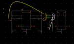
I have designed a two stage differential Amplifier with CMFB as shown in second picture of schematic for using it as Bipolar shaper . For the sake of stability, first i check phase of OTA which is 90 around and i understand, it is quite good.
Now i have to check for common mode and differential mode stability test and do stb analysis in cadence. I have some queries if some one can kindly comment/confirm/correct me on it :
1: For common mode stability i use cmdmprobe between CMFB and output of op AMP as shown in second picture and connect both terminals of shaper, Inp, Inm in first picture, to CM voltage.
Is it right?
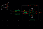
2: For differential mode, i break the feedback path and connect diffstrobe, as shown in first picture and connect the input, Inp & Inm in first picture, to some differential input voltages. Is it correct?
3: Is there any link between Phase margin of OTA and Loop gain Phase Margin?
4: Is there any link between Unity Gain Frequency of OTA and cross over frequency which we get in stability analysis?
Thanks in advance
Now i have to check for common mode and differential mode stability test and do stb analysis in cadence. I have some queries if some one can kindly comment/confirm/correct me on it :
1: For common mode stability i use cmdmprobe between CMFB and output of op AMP as shown in second picture and connect both terminals of shaper, Inp, Inm in first picture, to CM voltage.
Is it right?
2: For differential mode, i break the feedback path and connect diffstrobe, as shown in first picture and connect the input, Inp & Inm in first picture, to some differential input voltages. Is it correct?
3: Is there any link between Phase margin of OTA and Loop gain Phase Margin?
4: Is there any link between Unity Gain Frequency of OTA and cross over frequency which we get in stability analysis?
Thanks in advance