Welcome to our site! EDAboard.com is an international Electronics Discussion Forum focused on EDA software, circuits, schematics, books, theory, papers, asic, pld, 8051, DSP, Network, RF, Analog Design, PCB, Service Manuals... and a whole lot more! To participate you need to register. Registration is free. Click here to register now.
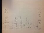
I have a few question regarding the common-emitter amplifier with classic / resistive bias
This is a problem from my class that we didn't get the solution
I have been working on them by myself and not feeling too sure about them
So I need someone with better understanding and knowledge to check my answer for me
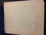
The resulting resistance is actually 365 K, I can just guess that you have chosen one-tenth applying a popular design rule. But if so, you should tell.
This site uses cookies to help personalise content, tailor your experience and to keep you logged in if you register.
By continuing to use this site, you are consenting to our use of cookies.