marinara27
Member level 1
hi everyone..
can someone explain to me about common emitter amplifier..
can someone explain to me about common emitter amplifier..
Follow along with the video below to see how to install our site as a web app on your home screen.
Note: This feature may not be available in some browsers.

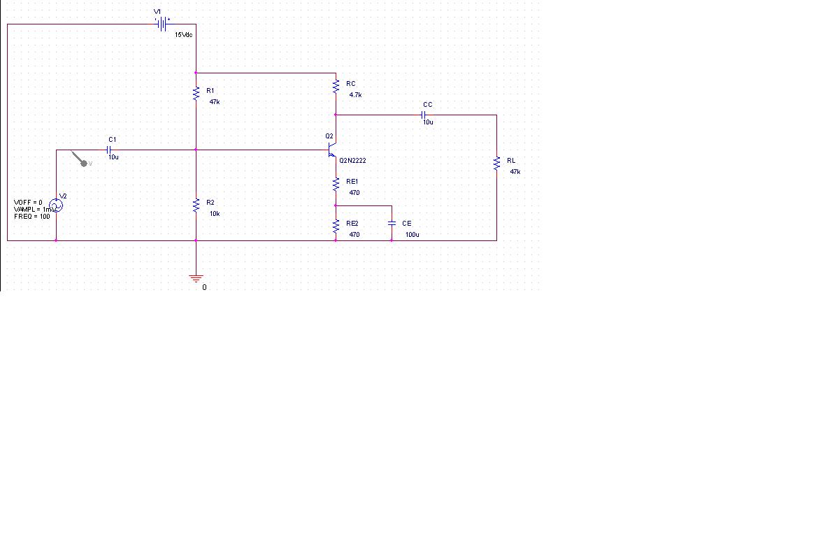
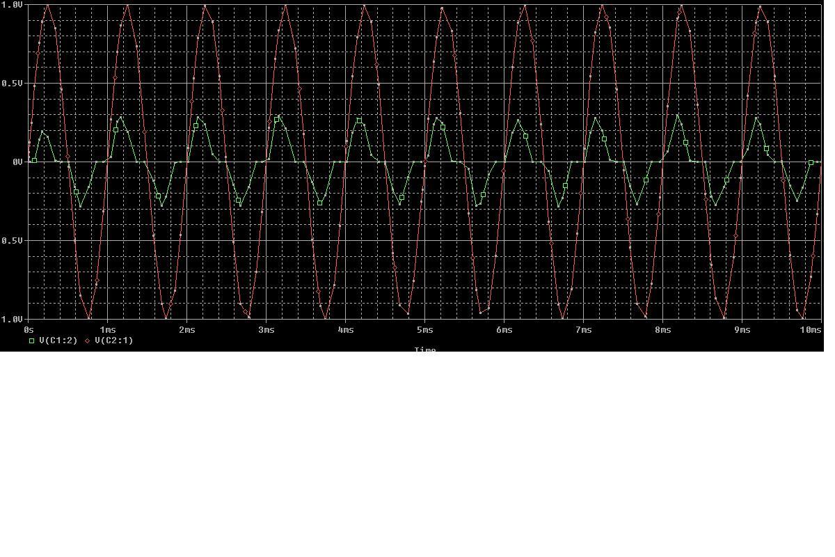
andi21 said:The important things that you should know in common emitter amplifier is:
*input wave=output wave
*Vce(voltage between common and emitter)= 2 Vcc
andi21 said:The important things that you should know in common emitter amplifier is:
*input wave=output wave
*Vce(voltage between common and emitter)= 2 Vcc
*The frequency response are two : for low freq and high freq
for low freq the formula is Gain=Rc/RE
for high freq the formula is Gain=Rc/(RE+re)
Rc(resistance in common)
RE(resistance in emitter)
re(resistance in Emmit on transistor)
*Capacitor value in emitter make a shift in frequency response in to the right
Higher its value, so the frequency cut off higher to
Its happen because capacitor slide over the high frequency so the high frequency doesn't through the RE.
I things that's enough
Andi
But the poster apparently doesn't read other threads.Someone else must be reading the same book!