Continue to Site

Welcome to EDAboard.com

Welcome to our site! EDAboard.com is an international Electronics Discussion Forum focused on EDA software, circuits, schematics, books, theory, papers, asic, pld, 8051, DSP, Network, RF, Analog Design, PCB, Service Manuals... and a whole lot more! To participate you need to register. Registration is free. Click here to register now.

Commercial inverter - Rectify the output - Capacitor

Status
Not open for further replies.

unavezmasysale

Member level 2
Joined
Mar 24, 2014
Messages
49
Helped
1
Reputation
2
Reaction score
1
Trophy points
8
Activity points
353
Dear,
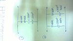
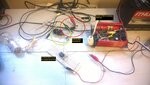
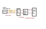
I need to rectify the output of a commercial inverter (Chinese - 12V to 220V - 250W) and then filter it to have a DC voltage.
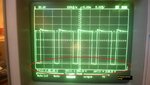
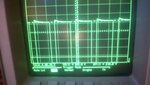
The rectifier works perfect, but when I connect two capacitors in series to achieve the necessary voltage [(220uF / 200V) x 2 series=> 110uF / 400V] the output became zero.
Which is the effect that the capacitors generate?
Can anyone help me?
Thanks in advance.
 

It is not practical to put capacitors in series with the idea they will 'share' a DC charge.

Eventually one capacitor is likely to take the entire charge. This is because their values cannot be precisely matched. After a number of cycles, the charges become severely imbalanced.

Almost certainly, one of your capacitors is ruined.
 

the high pulse current into the large caps causes an over-current error and the inverter shuts down...
 

I don't agree with the explanation. Capacitor series circuit is pretty common, particulaly for voltages above 400V. You should have balancing resistors to achieve equal voltage share, but even without, it's rather unlikely to damage the capacitors fastly.

There must be a different problem, e.g. inverter is stopping due to the capacitor inrush current. Or some trivial wiring fault.
 
I don't agree with the explanation. Capacitor series circuit is pretty common, particulaly for voltages above 400V. You should have balancing resistors to achieve equal voltage share, but even without, it's rather unlikely to damage the capacitors fastly.

Right, balancing resistors are essential.

If both capacitors are good, then there is not as drastic a problem as I described. Even in the case where one cap is 20% low, and the other 20% high, they will acquire uneven charges. But neither appears as though it will exceed the 200V rating mentioned in the OP.

The chief problem occurs in the case where one capacitor has internal leakage. Even with merely a few kOhm, it will eventually lose all its charge. Then the other capacitor (the good capacitor) will acquire the entire voltage. This could destroy it.

As you stated, the problem is reduced when balancing resistors are installed.
 
So try a couple of 100K resistors in series to split the voltage across the capacitors. If it does not spring to life, try a 100 ohms in series with the capacitors to limit their inrush current.
Frank
 
Thanks everyone guys!

I don´t understand how to balance the capacitors...Which of these is the correct:

1) Two differents networks in parallel of 100Kohm + 220uF/200V. (In the resistor drop the difference voltage)
2)One network with the four components, 100Kohm+100Kohm+200uF+200uF/200V ?
3) Other?

Thanks again!

- - - Updated - - -

Thanks everyone guys!

I don´t understand how to balance the capacitors...Which of these is the correct:

1) Two differents networks in parallel of 100Kohm + 220uF/200V. (In the resistor drop the difference voltage)
2)One network with the four components, 100Kohm+100Kohm+200uF+200uF/200V ?
3) Other?

Thanks again!

...
Number 3) Resistor 100ohm+220uF+220uF all in series.

thanks...
 

Attachments

  • WP_20150421_009.jpg
    WP_20150421_009.jpg
    240.1 KB · Views: 106

Where did you put the rectifier? What bridge or diodes do you use?
 

FvM, sorry the AN is not so clear for me. If I connect the resistor in parallel with the capacitor how will the resistor decrease the inrush current generated by the capacitors?
Can you help me with the approximate values of the the resistor and the capacitors if the output voltage is 400V and the current 1A?

One idea to solve this problem is to connect a resistor in series with the capacitors. In parallel with the resistor connect a SCR, two TAU after the init the SCR is active and the resistor is discard.
What do you think about this solution?

Vbase, the rectifier is before the filter(Capacitors and balance resistor). I am using 4 FR307 diodes.

Ψ
 

As FvM mentioned the resistors are in parallel with the caps, the job of the resistors is to balance the voltage on the caps, the resistors are not for limiting the inrush current.
You cannot use resistors to limit the inrush current because it will reduce the efficiency dramatically. Use an inductor. To limit the current to 2A it needs to be about 330mH, quite large in size. Put the inductor in series to the inverter output.
 
Last edited:
FvM, sorry the AN is not so clear for me. If I connect the resistor in parallel with the capacitor how will the resistor decrease the inrush current generated by the capacitors?

As said from the start, balancing has nothing to do with inrush currents. And yes, most likely balancing is not the actual problem you have. But you asked for a balancing circuit.

A practical solution for inrush current limiting can be a NTC, or a "pre-charge" resistor that is shorted by a relays after some delay. I would expect that some inverters are probably capable to start in presence of inrush currents, so generally speaking, it can be also seen as the case of an inverter which is unsuitable for your application.
 
FvM,
I connected a circuit with the rectifier diodes and 2 capacitors of 220uF/250V in series (~110uF/500V) with two series resistors of 1kohm. After two cycles TAU (ResxCap) a control circuit shorted the resistors through a relay. Once the control circuit short the resistors inverter´s voltage drop to zero as it be a short circuit.

The signal over the charge (lamp) is the same with the capacitors and without them. Why don´t the capacitors filter the output signal?

I attached some pictures to show the circuit and the output with the capacitor and the resistance and another one without them(both capacitors and resistors).
 

Attachments

  • WP_20150425_003.jpg
    WP_20150425_003.jpg
    437.8 KB · Views: 102
  • WP_20150425_005.jpg
    WP_20150425_005.jpg
    447.3 KB · Views: 100
  • WP_20150425_006.jpg
    WP_20150425_006.jpg
    336.8 KB · Views: 102

FvM,
I connected a circuit with the rectifier diodes and 2 capacitors of 220uF/250V in series (~110uF/500V) with two series resistors of 1kohm. After two cycles TAU (ResxCap) a control circuit shorted the resistors through a relay. Once the control circuit short the resistors inverter´s voltage drop to zero as it be a short circuit.

The signal over the charge (lamp) is the same with the capacitors and without them. Why don´t the capacitors filter the output signal?

I attached some pictures to show the circuit and the output with the capacitor and the resistance and another one without them(both capacitors and resistors).


Imagine all Caps as a short circuit with ESR (<1R?)

If you drain 1A from a resistive load with 10% ripple then the current pulse is on only 10% of the time approx and thus is 10x Iavg

Try this. Put one ot two 300W Halogen tubes in series with the relay. If using 230V it is <1.5 Ω and we know all tungsten bulbs have surge current of 10x or PTC of 10x so cold it MAY be ~ 150 mΩ, which may help keep the inverter happy for its OCP ( over current protection) after Relay is closed across charge R.
( Trick... if using rugged Halogen tubes as current limiters, when < 1/3 rated V they act as constant current sources. )

Then put on your Light bulb load test.

BTW This is really a bad way to generate light. But a tough Inverter test.

I would use Hi V LEDs on DC

Both Light bulbs and motors have a surge current 5~10x rated current, so Inverters cannot drive them
BRidge caps always have Surge current factor = 1 / %V ripple


- - - -
V balance on 2 series caps is a secondary problem for mismatched caps. and not related to this.
 
Sunny,
The charge will not be necessarily a lamp in the future. I'm using it because I have not got a resistance with such power capacity.
I connected a resistor of 10ohm in series with the relay and the circuit is working.
Thanks all of you, this forum is real helpful.

BR.
 

Guys,
Well, I will give more details about the projects to received from you, the possibilities of success.
The generator is the inverter that we are talking from the beginning, as I need to rectify the signal to obtain a DC voltage, I connect the capacitors and the limiter resistance.
The issue is that I need to have the possibilities to regulate the DC voltage, so I connect a Dimmer before the rectify (the charge will be 2kohm or more).
The problem is when the pulse after the rectify have small duty cycle. The current is so high so the Inverter autoprotect himself (overcurrent) and stop the output signal.
I do not want to use an inductor because as the frequency is so small it will be very large.
Can you give me some ideas? Is it possible?
I attached a block diagram to clear the idea.
Thanks again.

- - - Updated - - -

I will add some pictures that I took to the oscilloscope while the 10R series resistors was connected.
In one of the picture you could see the dimmer.
 

Attachments

  • Sin título.jpg
    Sin título.jpg
    35.4 KB · Views: 106
  • WP_20150426_012.jpg
    WP_20150426_012.jpg
    310.8 KB · Views: 105
  • WP_20150426_013.jpg
    WP_20150426_013.jpg
    301.4 KB · Views: 104
  • WP_20150426_014.jpg
    WP_20150426_014.jpg
    305.7 KB · Views: 92
  • WP_20150426_015.jpg
    WP_20150426_015.jpg
    327.5 KB · Views: 100
  • WP_20150426_016.jpg
    WP_20150426_016.jpg
    297.9 KB · Views: 99
  • WP_20150426_019.jpg
    WP_20150426_019.jpg
    286.5 KB · Views: 97
  • WP_20150426_020.jpg
    WP_20150426_020.jpg
    322.4 KB · Views: 98

Sunny,
The charge will not be necessarily a lamp in the future. I'm using it because I have not got a resistance with such power capacity.
I connected a resistor of 10ohm in series with the relay and the circuit is working.
Thanks all of you, this forum is real helpful.

BR.

I realized that all along as I have done the same.

I apologize I inverted my thinking and it is not a PTC you need but an NTC metal oxide part like a polyfuse but called an ICL

Cheap and any size then no relay required with the right choice.
https://www.digikey.com/product-sea...tion/inrush-current-limiters-icl/656273?k=icl
 
Any other suggestions?

I really need to solve this issue.

Thanks.
 

Since you failed to supply the critical OCP (Amps) threshold for the inverter, I can only guess

250W @ 250V = 1A Steady state max

10% ripple max @1A is thus 25V/1A ~ 22Ω std value
22Ω ICL = $1 https://www.digikey.com/product-sea...t=0&page=1&quantity=0&ptm=0&fid=0&pageSize=25

For frequency 100Hz Peak current will be 10x will still trip Inverter @10% V ripple. under Lamp load

The cold resistance is 220Ω, The hot resistance is 4 Ω (121'C) so mount 1cm above board with unrestricted convection air.

No relay required.

Buy >=4 ICL cheap so you can use in series or parallel to adjust.
 

Status
Not open for further replies.

Similar threads

Part and Inventory Search

Welcome to EDABoard.com

Sponsor

Back
Top