Continue to Site

Welcome to EDAboard.com

Welcome to our site! EDAboard.com is an international Electronics Discussion Forum focused on EDA software, circuits, schematics, books, theory, papers, asic, pld, 8051, DSP, Network, RF, Analog Design, PCB, Service Manuals... and a whole lot more! To participate you need to register. Registration is free. Click here to register now.

colpitts oscillator using crystal

Status
Not open for further replies.

Wajx93

Newbie level 2
Joined
Nov 18, 2012
Messages
2
Helped
0
Reputation
0
Reaction score
0
Trophy points
1,281
Activity points
1,297
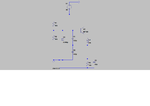
Hi,I would like to find out the values of Cs,Cp,Ls and Rs of the crystal for creating oscillations of 28Mhz. my circuit is:
colpitt.png

this only forms my first stage and the BF199 is important as i need to go on to make a 2W 85Mhz transmitter.
i have tried few values but the oscillations just won't start.
any suggestions?
plz help.
 

Hi,I would like to find out the values of Cs,Cp,Ls and Rs of the crystal for creating oscillations of 28Mhz. my circuit is:


this only forms my first stage and the BF199 is important as i need to go on to make a 2W 85Mhz transmitter.
i have tried few values but the oscillations just won't start.
any suggestions?
plz help.
Hi
What i can see ? did you really put that 1mH inductor , there ? in emitter path ? why such a huge value ? for 28 MHZ that's too large .
A question , why you didn't add , initial value of current for your capacitor ? i hope you know that each oscillator circuit , needs a transient value to start the oscillations .
A question : how you've selected values of each component ? randomly ? i can guide you through the right path ! ( i hope you know about oscillation condition and laws of oscillation ! hence you can easily find the correct values )
Best Wishes
Goldsmith
 

well initially i had to use a RF choke in that location but because i coudnt find that in my local lab so i had to do with an inductor as i was told it may work too.. its there to provide high impedance at the required frequency and let other frequencies pass all the way to the ground.
and well you could say that i placed C3 randomly.. the other resistors form a potential divider and Re resistance controls my required Ic so they are calculated.... the L and C3 are more on a whim definitely. Any proven way of their calculation will be highly appreciated. C1 and C2 are also calculated to be giving me the loop gain of more than 1.
 
Last edited:

well initially i had to use a RF choke in that location but because i coudnt find that in my local lab so i had to do with an inductor as i was told it may work too.. its there to provide high impedance at the required frequency and let other frequencies pass all the way to the ground.
Hi again
I know what is the duty of an RFC as well , hence description isn't required .
Why that huge value ?? you can easily change it's value . by clicking on it's value and then type every value that you want .

and well you could say that i placed C3 randomly.. the other resistors form a potential divider and Re resistance controls my required Ic so they are calculated.... the L and C3 are more on a whim definitely. Any proven way of their calculation will be highly appreciated. C1 and C2 are also calculated to be giving me the loop gain of more than 1.
If loop gain be higher than 1 you'll have THD . you should consider it , a bit greater than 1 . e.g 1.08 or 1.09 .
But for designing such oscillator , there some simple ways available too .
One of the simplest ways is that you inject a signal in your desired frequency of oscillation , and then measure AV and beta . and then change values till your AV*beta be greater than one ( a bit ) then you can remove that injected signal source ( my mean is in simulation ) then you can be sure that your circuit will oscillate as well .
but don't forget that this oscillator can oscillate in odd harmonics , or fundamental .
and for biasing resistors you can select them as VE be around 1 volts ( DC voltage ) and it should be able to create enough current gain . and you should consider large value of Zin because you've a crystal , there . and the other important factor is 10k ohms seems a bit large for RE . decrease it up to 1 or 2 k ohms . and use initial value for your simulations .
Good Luck
Goldsmith
 

Status
Not open for further replies.

Similar threads

Part and Inventory Search

Welcome to EDABoard.com

Sponsor

Back
Top