Continue to Site

Welcome to EDAboard.com

Welcome to our site! EDAboard.com is an international Electronics Discussion Forum focused on EDA software, circuits, schematics, books, theory, papers, asic, pld, 8051, DSP, Network, RF, Analog Design, PCB, Service Manuals... and a whole lot more! To participate you need to register. Registration is free. Click here to register now.

Colpit's Oscillator Problem,HELP!

Status
Not open for further replies.

Aveaqim

Newbie level 2
Joined
Dec 16, 2012
Messages
2
Helped
0
Reputation
0
Reaction score
0
Trophy points
1,281
Activity points
1,299
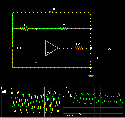
I am suppose to design a colpitt's oscillator with an oscillating frequency of 1Mhz, but im not getting any output, please someone,help me..i need some explaination aswell..im using C1:0.01uF,C2:0.1uF,L:2.789uH..maybe it is my resistors?im not sure, im really new at this..im suppose to do this with an op amp, so i'd appreciate it if we just stick to that.. Untitled.pngany help would be great.
 

Where did you get the circuit and component values? You apparently know how to calculate an oscillation frequency, but do you understand how it's related to OP dara?
 

Check your power supply connections. The 741 takes supply+ at pin 7.
It takes supply- at pin 4.

Spec sheet says supply V should not exceed +18 -18 bipolar. I don't know whether or not your simulator will let the op amp work with a greater amount.

Other than that, your schematic works okay in my simulation.

Screenshot:


The 741 output does not get within 2V to the negative rail. I used +12 and -10 for its upper and lower limits.

These are within safe specs for the power supply as per guidelines. The Falstad simulator does not run supply lines to an op amp.
 

Other than that, your schematic works okay in my simulation.
Seriously, do you expect that an OP with less than 1 MHz GBW is working in an 1 MHz oscillator? Other than the Falstad simulator, Multisim uses a LM741 model with bandwidth linitation.
 

Seriously, do you expect that an OP with less than 1 MHz GBW is working in an 1 MHz oscillator? Other than the Falstad simulator, Multisim uses a LM741 model with bandwidth linitation.

My National Semiconductor databook (1982 edition) gives 1.5 MHz as the bandwidth. I suppose a 1 MHz oscillator is near the limit of its capability. However in this circuit the op amp is only needed to boost the oscillations a little. Its output (pin 6) is an AC square wave, through a 100k resistor. I don't know how demanding an application this should be considered for a 741.

I should have pointed out that Falstad's uses ideal components.

The link below is my simulation as a runnable link.

https://tinyurl.com/c8ypozb

A recent thread was about this same topology (at a target frequency 10MHz).

https://www.edaboard.com/threads/273289/
 

My National Semiconductor databook (1982 edition) gives 1.5 MHz as the bandwidth. I suppose a 1 MHz oscillator is near the limit of its capability. However in this circuit the op amp is only needed to boost the oscillations a little. Its output (pin 6) is an AC square wave, through a 100k resistor. I don't know how demanding an application this should be considered for a 741.
I guess, you don't want to establish a new theory of oscillator operation, but the feedback amplifier must achieve a loop gain of > 1 to maintain oscillations. That's impossible in this circuit even with 1.5 MHz GBW.

I should have pointed out that Falstad's uses ideal components.
That's is in fact the only chance to see oscillations in this circuit. Besides real LM741 properties, also the required inductor Q makes it unlikely to see oscillations in a real circuit with the shown component values.
 
  • Like
Reactions: LvW

    LvW

    Points: 2
    Helpful Answer Positive Rating
I guess, you don't want to establish a new theory of oscillator operation, but the feedback amplifier must achieve a loop gain of > 1 to maintain oscillations. That's impossible in this circuit even with 1.5 MHz GBW.

Yes - no doubt about it. More than that, one should not forget the phase shift of an opamp-based amplifier working near its frequency limit.
 

so basically why my circuit is not producing any outputs is because of my op amp? guys ive tried using Falstad for the first time and im not getting any outputs like you guys got, is there something i should include? what does "Its output (pin 6) is an AC square wave" mean? thanks a bunch for the info btw
 

so basically why my circuit is not producing any outputs is because of my op amp? guys ive tried using Falstad for the first time and im not getting any outputs like you guys got, is there something i should include? what does "Its output (pin 6) is an AC square wave" mean? thanks a bunch for the info btw

My clickable link should contain all the parameters which allow the oscillator to run, even at 1 MHz.

However the oscillations start out very weak. It takes several hundred cycles for the amplitude to build up to 1V. The speed may need to be set higher.

what does "Its output (pin 6) is an AC square wave" mean?

It applies to the normal 8-pin dual in-line package. This Colpitts version needs for a bipolar supply to be hooked up. This allows the output to go negative and positive. It has to provide true AC in order to give the LC tank loop a boost every cycle.

Going back to your schematic, it has a UA741MU op amp. It looks like it should be a garden variety 741. However its pins are connected differently. Check the pinouts. You may want to try a different model.
 

Status
Not open for further replies.

Similar threads

Part and Inventory Search

Welcome to EDABoard.com

Sponsor

Back
Top