Continue to Site

Welcome to EDAboard.com

Welcome to our site! EDAboard.com is an international Electronics Discussion Forum focused on EDA software, circuits, schematics, books, theory, papers, asic, pld, 8051, DSP, Network, RF, Analog Design, PCB, Service Manuals... and a whole lot more! To participate you need to register. Registration is free. Click here to register now.

Coding for 5x7 LED Dot matrix in mikroC

Status
Not open for further replies.

chingfongkee

Newbie level 4
Joined
Jul 23, 2010
Messages
5
Helped
0
Reputation
0
Reaction score
0
Trophy points
1,281
Location
Malaysia
Activity points
1,324
hello everyone, i would like to ask about the LED Dot matrix
i'm new to this device and this is a 5x7 dot matrix
Below showing the small part of the programming coding to display alphabets A to Z..
anyone can explain the logic on the coding to display a alphabet A?
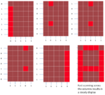
ColumnScanning.png


unsigned short Alphabets[130]={ 0x7e, 0×09, 0×09, 0×09, 0x7e, // A
0x7f, 0×49, 0×49, 0×49, 0×36, // B
0x3e, 0×41, 0×41, 0×41, 0×22, // C
0x7f, 0×41, 0×41,0×22, 0x1c, //D
0x7f, 0×49, 0×49, 0×49, 0×63, //E
0x7f, 0×09, 0×09, 0×09, 0×01, //F
0x3e, 0×41, 0×41, 0×49, 0x7a, //G
0x7f, 0×08, 0×08, 0×08, 0x7f, //H
0×00, 0×41, 0x7f, 0×41, 0×00, // I
0×20, 0×40, 0×41, 0x3f, 0×01, //J
0x7f, 0×08, 0×14, 0×22, 0×41, //K
0x7f, 0×40, 0×40, 0×40, 0×60, //L
0x7f, 0×02, 0×04, 0×02, 0x7f, //M
0x7f, 0×04, 0×08, 0×10, 0x7f, //N
0x3e, 0×41, 0×41, 0×41, 0x3e, //O
0x7f, 0×09, 0×09, 0×09, 0×06, //P
0x3e, 0×41, 0×51, 0×21, 0x5e, //Q
0x7f, 0×09, 0×19, 0×29, 0×46, //R
0×46, 0×49, 0×49, 0×49, 0×31, // S
0×01, 0×01, 0x7f, 0×01, 0×01, //T
0x3f, 0×40, 0×40, 0×40, 0x3f, //U
0x1f, 0×20, 0×40, 0×20, 0x1f, //V
0x3f, 0×40, 0×30, 0×40, 0x3f, //W
0×63, 0×14, 0×08, 0×14, 0×63, //X
0×07, 0×08, 0×70, 0×08, 0×07, //Y
0×61, 0×51, 0×49, 0×45, 0×43 // Z
};
 

Logic is multiplexing... You need to implement it by utilizing the property of our eye - ' persistence of vision'

Try this link, I hope you will get something...
 
  • Like
Reactions: zia

    zia

    Points: 2
    Helpful Answer Positive Rating
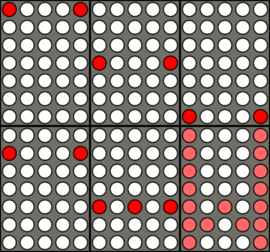
well the image you attached explains everything. Anyway, check out my figure below which may explain the hex pattern for character 'A' on 5x7 led display.

Code:
//------------------------------------
//     Example font pattern for 'A'
//     ¯¯¯¯¯¯¯¯¯¯¯¯¯¯¯¯¯¯¯¯¯¯¯¯¯¯¯
//         {0x7e,0x09,0x09,0x09,0x7e} //A
//           |    |    |    |    |    
//           |    |    +--+ | +--     
//           |    +-----+ | | | 
//           +--------+ | | | | 
//                    | | | | | 
//                    _________
//      PORTB.0  ->  |0|1|1|1|0| LSB
//      PORTB.1  ->  |1|0|0|0|1|
//      PORTB.2  ->  |1|0|0|0|1|
//      PORTB.3  ->  |1|0|0|0|1|
//      PORTB.4  ->  |1|1|1|1|1|
//      PORTB.5  ->  |1|0|0|0|1|
//      PORTB.6  ->  |1|0|0|0|1| MSB
//                    ¯¯¯¯¯¯¯¯¯
//

bit 1 = LED on

only one column is enabled at a time.

first 0x7e is loaded into port and column 1 is enabled and rest off (see the first pattern in your figure)
then 0x09 is written to port and column 2 is enabled and rest column off (see the second pattern in your figure)
then 0x09 is written to port and column 3 is enabled and rest column off
then 0x09 is written to port and column 4 is enabled and rest column off
then 0x7e is written to port and column 5 is enabled and rest column off (see the fifth pattern)

now the above sequence is repeated very fast so we see all the column pattern combined (see the sixth pattern in your figure)

Result = character 'A' in 5x7 led matrix display!
 

Thanks s_guria for your attached but i'm still find something wrong in your pattern:
//------------------------------------
// Example font pattern for 'A'
// ¯¯¯¯¯¯¯¯¯¯¯¯¯¯¯¯¯¯¯¯¯¯¯¯¯¯¯
// {0x7e,0x09,0x09,0x09,0x7e} //A
// | | | | |
// | | +--+ | +--
// | +-----+ | | |
// +--------+ | | | |
// | | | | |
// _________
// PORTB.0 -> |0|1|1|1|0| LSB
// PORTB.1 -> |1|0|0|0|1|
// PORTB.2 -> |1|0|0|0|1|
// PORTB.3 -> |1|0|0|0|1|
// PORTB.4 -> |1|1|1|1|1|
// PORTB.5 -> |1|0|0|0|1|
// PORTB.6 -> |1|0|0|0|1| MSB
// ¯¯¯¯¯¯¯¯¯
//

I find that the three column 0x09 must replace by this value in HEX 0x11

Please verify my reply if it's all ok.

Thanks
 

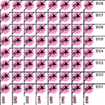
Led matrix is the array of a group of LED . In which each LED can controlled
The above picture is an 8x8 LED matrix .Here we can control each LED by applying supply to any columns to row .(DR1 to DR8 - rows ) (DC1 to DC8- columns ).Display Technique Every displays take an disadvantage of our eyes lacks known as Persistence of visionThat is the display shows the data (ie the LED blinks) at a time (only rows or columns)By controlling the flow of electricity through each row and column pair it is possible to control each LED individually. By scanning across rows, quickly flashing the LEDs on and off, it is possible to create characters or pictures to display information to the user. The refresh rate is typically fast enough to prevent the human eye from detecting the flicker.
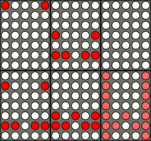
if don't you understand look at the picture below

LED matrix display scanning by rows to make the letter WHere the Row scans first as slowly .after it running speedily due to our Persistence of vision we can see as a letter W this is the technique .


Make First A letter to display(Before making Moving Display Now you want to select a controller .select one which one you are fa miler.i am describing here most popular controller 89S51 (Atmel 8051 famly)
 

Attachments

  • 20070823083907580 (1).png
    20070823083907580 (1).png
    172.4 KB · Views: 94
  • 100px-Dot_matrix.gif
    100px-Dot_matrix.gif
    137 KB · Views: 135

Status
Not open for further replies.

Part and Inventory Search

Welcome to EDABoard.com

Sponsor

Back
Top