Continue to Site

Welcome to EDAboard.com

Welcome to our site! EDAboard.com is an international Electronics Discussion Forum focused on EDA software, circuits, schematics, books, theory, papers, asic, pld, 8051, DSP, Network, RF, Analog Design, PCB, Service Manuals... and a whole lot more! To participate you need to register. Registration is free. Click here to register now.

CMOS threshold voltage vs speed and leakage power

Status
Not open for further replies.

aruna1

Member level 1
Joined
Jun 18, 2009
Messages
40
Helped
1
Reputation
2
Reaction score
1
Trophy points
1,288
Activity points
1,602
Hi all,
I'm reading on CMOS and came across following fact

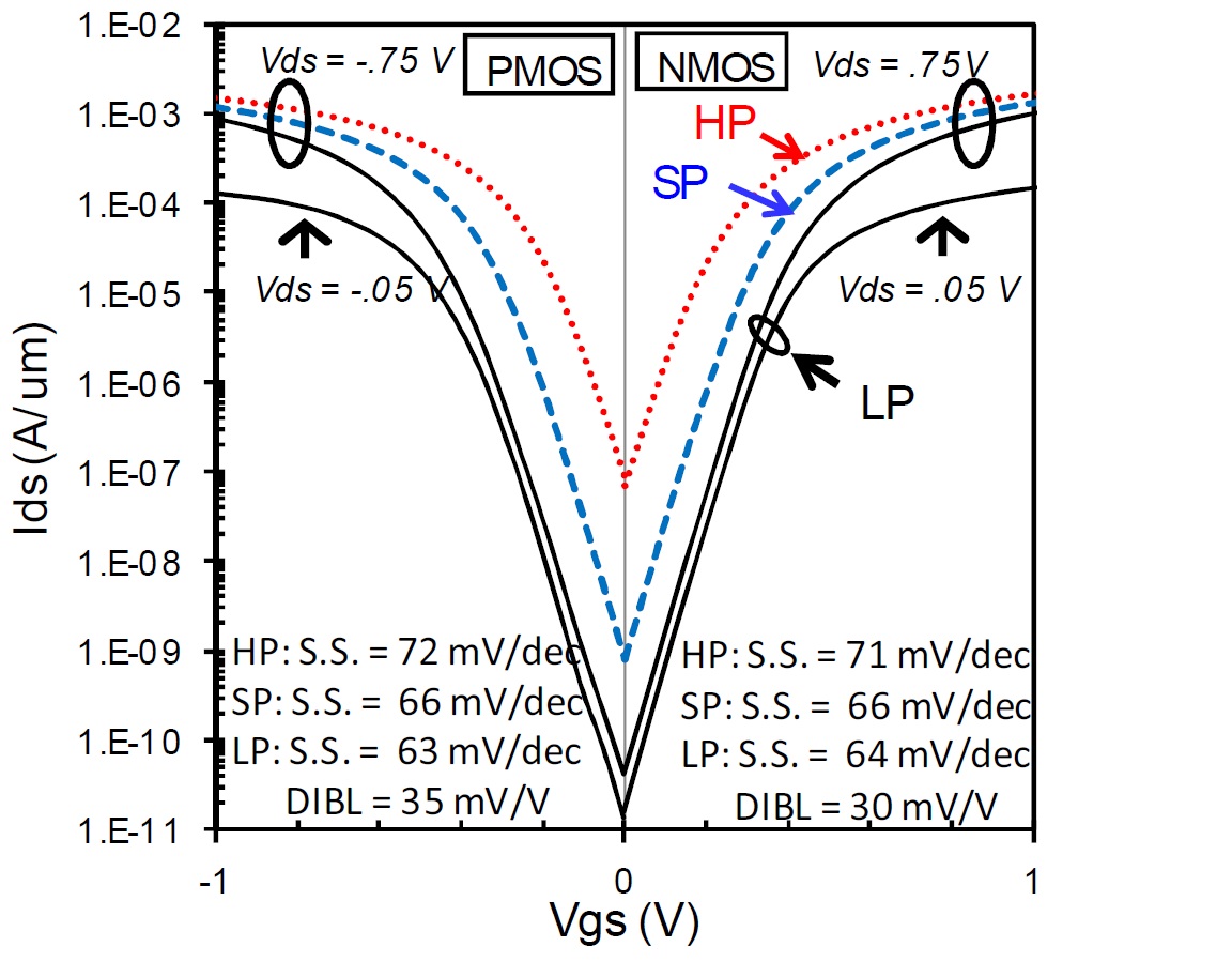
CMOS with low threshold voltage (lvt) is used in high-speed (time critical) designs but they have higher leakage power consumption
CMOS with high threshold voltage (hvt) is used in low-speed (not time critical) designs but they have lower leakage power consumption

I was searching through the internet but couldn't find any information explain how low threshold voltage is fast but consume more power and how high threshold voltage is slow but consumes low power.

All the documents I came across simply states "lvt is for fast, and hvt is for slow,low power"

So can somebody please explain how FET with low threshold voltage has higher speed and higher leakage current while FET with high threshold will be slow but low on power?

Thank you very much.
 

Well, many textbooks will tell you about the relation of
VT to "off" leakage (subthreshold slope) and drive
strength (basic MOS drain current eqn). Drive strength
and capacitance give you risetime, delay is risetime/2
pretty much.

You have of course other dimensions such as drawn L,
for reducing leakage.
 

Assuming same input capacitance and dimentions, from off state, LVT transistors will be triggered-on earlier than HVT by the rising gate voltage. (e.g. LVT gate=0.2v vs HVT gate=0.3v exaggerated for next point).
This is a problem in leakage power since gate voltage has to drop significantly below threshold to shutdown the transistor. (HVT is already off at 0.15v, LVT still leaking.)
 

Well, many textbooks will tell you about the relation of
VT to "off" leakage (subthreshold slope) and drive
strength (basic MOS drain current eqn). Drive strength
and capacitance give you risetime, delay is risetime/2
pretty much.

You have of course other dimensions such as drawn L,
for reducing leakage.

Thanks dick_freebird
I came across an equation for Ids vs Vt, but nothing for Ioff vs Vt

Assuming same input capacitance and dimentions, from off state, LVT transistors will be triggered-on earlier than HVT by the rising gate voltage. (e.g. LVT gate=0.2v vs HVT gate=0.3v exaggerated for next point).

Thanks mask_layout,

yes since in LVT threshhold voltage is low turning on from off position will be fast, but what about turning off the device from on position? since threshhold voltage is low (0.2V) if the applied gate voltage is 1V it will need to drop atleast 0.8V to turn off the LVT transistor.
This is a problem in leakage power since gate voltage has to drop significantly below threshold to shutdown the transistor. (HVT is already off at 0.15v, LVT still leaking.)

Agreed
 

Difference between lvt and hvt is concentration of doping, oxide thickness and threshold voltage of course.
In case of lvt, conc. of doping and oxide thickness is more compare to hvt.. And this the reason that more the doping, so more speed and more leakage compare to hvt.

thanx.


Attached are the IV curves of 3 different Vts of Intel's 22nm FinFET process (IEDM 2012). They call their Vts HP (High performance), SP (Standard Perf) and LP (Low Power), which are roughly equivalent to hvt, rvt, lvt if you work with foundry processes. You can think of Vth as the voltage threshold where the transistor turns on. Process engineers use numerous different methods to get multiple Vts but the common ones are channel doping, gate oxide, channel length and work function modification. Now without getting into deeper device physics, you can imagine that as Vth is modified using any of the methods mentioned before, the IV curve shifts to the 'right' or 'left'. Looking at the NMOS curve (right box), imagine the black line move from right to left...giving you the blue and red curves, the leakage floor (current at Vgs=0) increases, but the device turns on quickly and it has higher Idsat (current at Vgs=VDD). Since leakage is an exponential fuction, for every 10-15% higher Idsat, you get about 10X increase in leakage, as seen in the figure. Hence, HVT or higher vt devices are slower (less current) but also low power due to lower leakage current and vice versa.

Hope this helps.
 

Status
Not open for further replies.

Part and Inventory Search

Welcome to EDABoard.com

Sponsor

Back
Top