Continue to Site

Welcome to EDAboard.com

Welcome to our site! EDAboard.com is an international Electronics Discussion Forum focused on EDA software, circuits, schematics, books, theory, papers, asic, pld, 8051, DSP, Network, RF, Analog Design, PCB, Service Manuals... and a whole lot more! To participate you need to register. Registration is free. Click here to register now.

CMOS inverter with output glitch

Status
Not open for further replies.

oAwad

Full Member level 2
Joined
Feb 15, 2017
Messages
136
Helped
0
Reputation
0
Reaction score
0
Trophy points
16
Activity points
1,312
Hello,

If I have a simple CMOS inverter with input= '1'. Hypothetically speaking, if the output gets somehow an intentional glitch/noise that's greater than NMOS threshold voltage, can the input of the inverter toggel ?

I have simulated this behavior in SPICE, where input='1' and I insert a glitch at the output greater than threshold of NMOS...I thought the inverter would overcome such glitch and remain with same values (input =1' and output '0'). However, in the simulation the output was raised to '1' and the input changed to '0' (as if the inverter working backward: output -> input).

Can any experienced one tell me how this happened in some details ?

Thanks
 

This certainly depends on the
  • impedance of the glitch source at the output
  • impedance of the input source
  • supply voltage in relation to the threshold and glitch voltage
Could you show your test bench?
 

The "glitch" would have to be sharp enough that it can
back-couple across CdgN and CdpG, enough to push
CgsN and CgsP past logic threshold (presumably from
a well-driven "resting" VIH/VIL) against the shunt loads
of output (RonN) and input (RonP). Just the capacitive
division alone suggests you'd need a full scale "glitch"
on the output to get close to half scale "glitch" on the
input, and this discounts input wireload and co-fan-in.
Presumably you are not talking about beyond-rail
amplitudes, or backing impedances lower than another
logic gate.

Now how you would cause a voltage source driven
input to change its state, I couldn't imagine.

But if you were (say) using pass-transistor-logic
styles, this (weakly driven input with as small a
shunt C as possible) and perhaps an input left to float
hoping it will "remember" its state, this sort of thing
might well happen.

Of course you might descend into the inverter
schematic and make sure "a" (input) and "y" (output)
aren't simply swapped....
 

This certainly depends on the
  • impedance of the glitch source at the output
  • impedance of the input source
  • supply voltage in relation to the threshold and glitch voltage
Could you show your test bench?

This inverter is part of a big project so it's hard to provide a helpful test bench in this case. But here are all the values:

1) output impedance of the inverter: 77.5 ohm
2) input impedance of glitch source: approx. infinity
3) supply voltage: 1.1 V / glitch peak: 676.6 mV / NMOS threshold (VTH): 0.54 V

You can also tell me your intuition behind these questions so that I can think from this point. What made you think of impedance, does the transistor have a minimum I(ds) current to work ? maybe this glitch decreased the I(ds) beyond this threshold current ? If yes, still what made the input of the inverter to change ?

Thanks!
 

1) output impedance of the inverter: 77.5 ohm
2) input impedance of glitch source: approx. infinity
3) supply voltage: 1.1 V / glitch peak: 676.6 mV / NMOS threshold (VTH): 0.54 V

You can also tell me your intuition behind these questions so that I can think from this point. What made you think of impedance ... ?

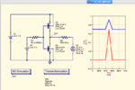
The #2) input impedance of glitch source: approx. infinity ... isn't helpful. I asked for the output impedance: it has to fight against the inverter's output impedance. Anyway, I can't see how a positive glitch ("greater than threshold of NMOS") could flip the inverter: the capacitively coupled glitch at the input (its height depends on the impedance of the input source, that's why I asked for) then is also positive and so supports the original state, s. this. picture:
inv_with_glitch.png
 

Status
Not open for further replies.

Similar threads

Part and Inventory Search

Welcome to EDABoard.com

Sponsor

Back
Top