ljy4468
Full Member level 4
- Joined
- Jul 20, 2005
- Messages
- 232
- Helped
- 13
- Reputation
- 26
- Reaction score
- 1
- Trophy points
- 1,298
- Location
- South Korea
- Activity points
- 3,023
https://obrazki.elektroda.pl/24_1185873737.jpg
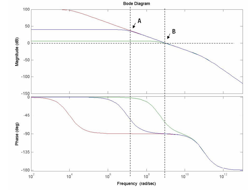
In above picture, I modeled b=1/2(green line),b=1/100(blue line)
open loop(red line) with matlab. (b=beta=feedback factor)
Then, If I made closed loop amp with b=1/100(blue line),
PhaseMargin is at point A with red line (~90 degree)
Now I've a question,
why we see redline (open loop phase function) instead of blue line(closed loop phase function)??