Continue to Site

Welcome to EDAboard.com

Welcome to our site! EDAboard.com is an international Electronics Discussion Forum focused on EDA software, circuits, schematics, books, theory, papers, asic, pld, 8051, DSP, Network, RF, Analog Design, PCB, Service Manuals... and a whole lot more! To participate you need to register. Registration is free. Click here to register now.

clock with day selector

Status
Not open for further replies.

gauravkothari23

Advanced Member level 2
Joined
Mar 21, 2015
Messages
640
Helped
5
Reputation
10
Reaction score
4
Trophy points
1,298
Activity points
6,922
Hi all,,,,
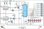
I just wanted to make a clock with alarm circuit using seven segment display.
i just got the ready circuit from google. but i did not understood the dipslay's used in this circuit. am attaching the circuit.... please let me know what kind of display's are used in this circuit. because it was not even mentioned in the page i downloaded from.
 

Attachments

  • Circuit.jpg
    Circuit.jpg
    77.9 KB · Views: 55

You can't just show a picture of a rectangle with "watch module" written inside of it and expect anybody to have the slightest idea what it is. You need more information.
 

thats what i mean to say.... i have checked the page from which i have downloaded..... its written nothing.... not any specificatoin or descrption about the watch module.
only written on the page is:
Alarm Clock With Day Selector
This circuit disables an alarm clock on Saturdays and Sundays when people like to sleep in but enables normal operation on Mondays to Fridays so that people rise in time for work or school. The core of the circuit is a 4017 decade counter which acts as the day counter and it is used in conjunction with a desk clock which acts the alarm and a watch module with alarm function which provides one clock pulse very day to the 4017. In operation, the watch module feeds a day pulse via transistor Q3 to the clock input of IC1. This has seven outputs connected via day switches (S1-S7) and diodes D3-D9 to Q1 which disables the alarm signal to the speaker via transistor Q2. LEDs1-7 indicate the actual day (if you forget!).

To set the system, set the desk clock for the correct time and for the desired alarm time (eg, 6’o’clock). The watch module is set to the correct time and its alarm set to midnight. The day counter, IC1, is set to the correct day, as indicated by the LEDs, by pushing switch S12 and closing switch S8 or S9. S8 is normally left open to conserve the battery by leaving the LEDs off. As shown on the circuit, switches S1-S7 are set to sound the alarm on Mondays to Fridays and disable it on Saturday and Sunday. However, you can change the days to suit your work habits.
 

Status
Not open for further replies.

Part and Inventory Search

Welcome to EDABoard.com

Sponsor

Back
Top