syntaxerror247
Newbie level 2
Clock Pulse Generator
Hi,
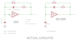
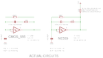
I want to make a variable (0.2 Hz - 1kHz) clock/pulse generator AND display the generated frequency value (e.g. 1024 Hz) on a 16x2 LCD display or to 7-segment display. I was going to use a 555 timer with a potentiometer to vary the output frequency of the 555, but a friend told me the output of the 555 is not that accurate due to the resistors and capacitors used with the 555 IC.
What do I need this for?: I'm trying to make a small logic trainer and need a variable clock signal generator to use for experiments with 74HC series ICs such as JK F/F and other ICs. It must be able to display the value of the frequency on the output display in real-time as the knob is turned.
Questions:
1- Should I use the 555 to make this circuit? or is there better ways to achieve my goal or making a variable clock generator? I'm open to better ideas and suggestions.
2- How do I make an accurate clock signal that I can vary using a mechanical device such as a potentiometer or maybe a keypad?
3- How do I count the output frequency?
4- How do I display the frequency value on an LCD or 7-segment display (whichever is easier)?
I know a bit about electronics theory (digital and analog) but haven't built any projects yet. This will be my first project.
Hi,
I want to make a variable (0.2 Hz - 1kHz) clock/pulse generator AND display the generated frequency value (e.g. 1024 Hz) on a 16x2 LCD display or to 7-segment display. I was going to use a 555 timer with a potentiometer to vary the output frequency of the 555, but a friend told me the output of the 555 is not that accurate due to the resistors and capacitors used with the 555 IC.
What do I need this for?: I'm trying to make a small logic trainer and need a variable clock signal generator to use for experiments with 74HC series ICs such as JK F/F and other ICs. It must be able to display the value of the frequency on the output display in real-time as the knob is turned.
Questions:
1- Should I use the 555 to make this circuit? or is there better ways to achieve my goal or making a variable clock generator? I'm open to better ideas and suggestions.
2- How do I make an accurate clock signal that I can vary using a mechanical device such as a potentiometer or maybe a keypad?
3- How do I count the output frequency?
4- How do I display the frequency value on an LCD or 7-segment display (whichever is easier)?
I know a bit about electronics theory (digital and analog) but haven't built any projects yet. This will be my first project.
Last edited: