Continue to Site

Welcome to EDAboard.com

Welcome to our site! EDAboard.com is an international Electronics Discussion Forum focused on EDA software, circuits, schematics, books, theory, papers, asic, pld, 8051, DSP, Network, RF, Analog Design, PCB, Service Manuals... and a whole lot more! To participate you need to register. Registration is free. Click here to register now.

clock duty cycle conversion

Status
Not open for further replies.

nanock

Member level 1
Joined
Mar 13, 2011
Messages
40
Helped
1
Reputation
2
Reaction score
1
Trophy points
1,288
Activity points
1,564
Hi,
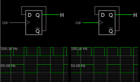
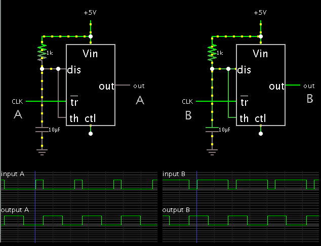
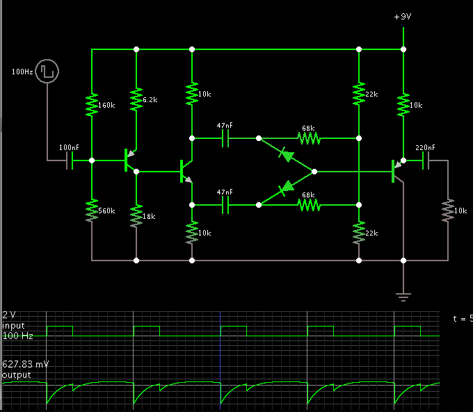
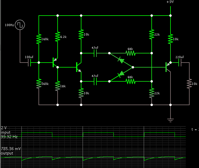
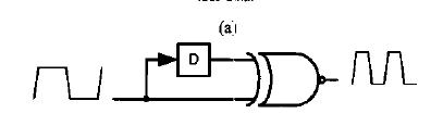
I have two clock outputs, one with 60% duty cycle and the other one with 40% duty cycle. I want to convert one of these, no matter which one will be, to 50% duty cycle.
Is it possible?
How can I convert a 60% or 40% duty cycle to 50% ?

thanks
 

u means add this two output 60 and 40 % and simply dived by 2 to get 50% duty cycle bro????
 
  • Like
Reactions: nanock

    nanock

    Points: 2
    Helpful Answer Positive Rating
These simulations show a divide-by-2 counter. It automatically gives you 50 percent duty cycle (at half the frequency):


These simulations show a 555 IC configured as a 'one-shot', triggered by each incoming clock pulse. It must be adjusted carefully to output the desired pulse length.

 
  • Like
Reactions: nanock

    nanock

    Points: 2
    Helpful Answer Positive Rating
with the same frequency, I imagine, if not, add a divider by 2 :)
I must try it but I want the same frequency with just a change in duty cycle.
thanks

- - - Updated - - -

u means add this two output 60 and 40 % and simply dived by 2 to get 50% duty cycle bro????
No, I just want to convert one of these 60% or 40% clocks to 50% clocks. All frequencies are the same. Just a little change in duty cycle.

- - - Updated - - -

These simulations show a divide-by-2 counter. It automatically gives you 50 percent duty cycle (at half the frequency):


These simulations show a 555 IC configured as a 'one-shot', triggered by each incoming clock pulse. It must be adjusted carefully to output the desired pulse length.

Thanks about simulations, but it changes the frequency. If you use D-Latch instead of DFF, will the frequency change ? I just want to change the duty cycle to 50%.
 

it is close to an analog design.

We did a project a digital clock multiplier by two (long time ago), so then you could divide by two and have a 50% duty cycle, but you need to be very carefully with the backend steps.
The idea is xor with the same signal on both input, but one input has multiple buffers/delay (25% of the input signal).
 
  • Like
Reactions: nanock

    nanock

    Points: 2
    Helpful Answer Positive Rating
it is close to an analog design.

We did a project a digital clock multiplier by two (long time ago), so then you could divide by two and have a 50% duty cycle, but you need to be very carefully with the backend steps.
The idea is xor with the same signal on both input, but one input has multiple buffers/delay (25% of the input signal).
Unfortunately I'm not allowed to use analog tricks. But I think there is a solution with xor. I will tell you when ever I reach to a digital solution.
Thanks to all
 

Unfortunately I'm not allowed to use analog tricks. But I think there is a solution with xor. I will tell you when ever I reach to a digital solution.
Thanks to all
I think that use of duty cycle correction circuit(DCC) is critical. But one can find this helpful if I use DFF for divided by 2 so that I have 50% duty cycle and then utilizing frequency doubler to reach the original frequency.
If there is any other key point please tell me?
thanks
 

Lacking a transition at the 50 percent mark...

Therefore we must start where there is a transition, and construct a time-dependent feature of some kind.

Time-dependent components include coils and capacitors. In other words, analog constructs.

- - - Updated - - -

You mentioned a frequency doubler. Not a bad idea.

This simulation shows what you'll get:


The incoming transitions determine the shape of the output. The output is not at a 50 percent duty cycle.

- - - Updated - - -

Hold the phone, however. Your idea was to get 50 percent duty cycle pulses, at 1/2 the frequency, from a flip flop.

In that case the frequency doubler does provide 50 percent duty cycle output:

 
  • Like
Reactions: nanock

    nanock

    Points: 2
    Helpful Answer Positive Rating
Lacking a transition at the 50 percent mark...

Therefore we must start where there is a transition, and construct a time-dependent feature of some kind.

Time-dependent components include coils and capacitors. In other words, analog constructs.

- - - Updated - - -

You mentioned a frequency doubler. Not a bad idea.

This simulation shows what you'll get:


The incoming transitions determine the shape of the output. The output is not at a 50 percent duty cycle.

- - - Updated - - -

Hold the phone, however. Your idea was to get 50 percent duty cycle pulses, at 1/2 the frequency, from a flip flop.

In that case the frequency doubler does provide 50 percent duty cycle output:


In order to use an ordinary frequency doubler, I use an xor gate as below. But one problem I find is the delay cell. This cell must have 50% or 25% delay of input signal period. Can I use shift register as a delay cell?
1217489100_1382629673.png
 

Status
Not open for further replies.

Part and Inventory Search

Welcome to EDABoard.com

Sponsor

Back
Top