Continue to Site

Welcome to EDAboard.com

Welcome to our site! EDAboard.com is an international Electronics Discussion Forum focused on EDA software, circuits, schematics, books, theory, papers, asic, pld, 8051, DSP, Network, RF, Analog Design, PCB, Service Manuals... and a whole lot more! To participate you need to register. Registration is free. Click here to register now.

Class G amplifier design, (+/-)100V / (+/-)200V 1A, 400Hz

Status
Not open for further replies.

Easy peasy

Advanced Member level 6
Joined
Aug 15, 2015
Messages
4,666
Helped
1,396
Reputation
2,792
Reaction score
1,899
Trophy points
1,393
Location
Melbourne
Activity points
25,836
Hello all, we are looking to make some in house test gear - for this we need a linear source +200V to - 200V sine wave, 1A

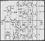
Glass G looks to be a good low noise solution ( switch mode too noisy ), and a wee bit more efficient than class AB

does anyone have the bones of a good class-G design that could be scaled up to the 200Vpk ( 400Vp-p ) needed

or point to real circuit links that might be useful - please? ( BJT / IGBT / mosfet / SiC mosfet all OK )

kind regards, EP.
 

What is the load for the very high voltage but fairly low current?
Audio amplifiers are the opposite, very high current at fairly low voltage.
 
I would go for class H (continuously variable power rails), look up the well respected Lab Gruppen pro-audio amps for idea's (schematics freely available).
Load impedance is simply a matter of design as I am sure you are aware.
 

@ Fourtytwo, class H uses switching supplies - which per the post are too noisy - please re-read the post more carefully before typing

@ Audioburu, as stated in the post - it is for some in house test gear - a simple but careful read would have obviated the need for your question

@ educated engineers, if some one out there has a useful contribution - I would be pleased to see it

kind regards,
 

I would go for class H (continuously variable power rails), look up the well respected Lab Gruppen pro-audio amps for idea's (schematics freely available).
Load impedance is simply a matter of design as I am sure you are aware.
Haven't looked into schematics of the Lab Gruppen, but wouldn't the voltage levels become a problem for the zener diodes?
 

@ prototyp_V1.0 we have access to fairly high power zeners, class G looks good - we may even go to 3 levels of voltage for each polarity - and we may drive them in bridge too ...
kind regards,
 

@ Auidogubu there are in fact electrostatic speaker drivers that go up to several kV, i.e. low current and high volts - some what in contrast to your post above ....
 

@ Fourtytwo, class H uses switching supplies - which per the post are too noisy - please re-read the post more carefully before typing

As you were discussing classes it was reasonable to assume that in switching you were referring to class-D. You seem extremely ready to criticise people who are trying to help you in a derogatory and rude manner. If you have already made your mind up about the solution then why bother posting a question here. As for class-H your assumption is incorrect. And don't worry I shall never type anything in response to any post of yours ever again!
 
not a reasonable assumption - class G, not D, I did not refer to any switching - my post refers to class G designs - in big letters - why can't people read rather than scan and type before brain is in gear ... ?
 

From about 30 seconds of reading it seems to me
that Class G is really just a Class AB amp and the
trick of "calling the power supply somebody else's
problem" and for any efficiency those supplies
-will- be switchers.

Now I have some nice cheap 30V Chinese power
supplies that are switchers and I can't see more
than a few mV of broadband noise on them. Just
how clean does this high voltage sine wave have
to be? If you haven't quantified then you can't
judge options.

What's so wrong with Class D, anyway? Seems to
be winning in car audio. Bridgable for as stupid
as you want to get. Clean enough to listen to I
would imagine. Probably all about the filters in the
end.
 

Geez, switching at the high volts required makes more noise than you can comprehend - class G is stepped class B - so quite a bit more efficient than single ( split ) supply class AB .... hence the request.

So far nobody has addressed the question directly - is there a lack of expertise? or just reading comprehension ... ?
 

@ Auidogubu there are in fact electrostatic speaker drivers that go up to several kV, i.e. low current and high volts - some what in contrast to your post above ....
I saw and heard electostatic speakers about 50 years ago driven from a special vacuum tubes amplifier. They produded a lot more than only 400Hz.
The system in this post is a secret.
 

Apologies to all - but just really seeking input as to Class G design - the load will be largely resistive with 0.8 PF lagging - I am now leaning towards 3 rails, +/-100V +/-200V & +/- 310VDC as the lowest loss design for an output ( now increased ) of 600Vpp at 2 amps rms.

As stated above the main test freq is 400Hz - but the amp will be DC coupled, allowing 0 - 400Hz

We do not need clean 0v x-over, and can tolerate small glitches as the rails are crossed - as it is mainly a power/endurance test

The rails will be supplied from ultra quiet switchers, and we may use BJT's for the 100V & 200V level, and 400V fets for the 310V level - with substantial zener protection across each.

The whole circuit and drive is pretty simple for 2 level - per the image attached - was hoping for tips and tricks from someone who may have designed similar as we build a 3 (6) level version ...

kind regards,
 

Attachments

  • class G 6.JPG
    class G 6.JPG
    76.3 KB · Views: 297

I'm not completely clear about possible alternative definitions, but according to the literature I have seen, class G is described as using one inner pair of linear output transistors and one or multiple outer switch pairs. The topology in your schematic is designated class H in this literature.

Of course both topologies are serving the same purpose of optimizing the power supply. A third variant, alternatively running under the label class G or H, uses variable boost or buck stages around the linear pair.

Just want to show that the classes are not really unequivocal. Of course they are only letters, finally the function matters.
 

Class G uses multiple power supply rails ( fixed ) and effectively series transistors which are turned on as the output level is driven higher - the picture above describes it exactly for a 2 voltage system ...
 

Maybe 15 or 20 years ago Philips made a Class-G power amplifier IC but it did not sell well and was replaced by better class-D amplifiers.
 

Class G uses multiple power supply rails ( fixed ) and effectively series transistors which are turned on as the output level is driven higher - the picture above describes it exactly for a 2 voltage system ...

My point is wheter the outer transistor are linear operated or switched.

In my literature, the topology with linear operated T2 and T4 (as in post #13 and the schematic below) is named class H. In class G, T2 and T4 are operated as switches, controlled by comparators, respectively they have lower power dissipation.

1601630706613.png


I don't claim this terminology as exlusively correct, just wanted to mention that there are different views.
 

Apologies to all - but just really seeking input as to Class G design - the load will be largely resistive with 0.8 PF lagging - I am now leaning towards 3 rails, +/-100V +/-200V & +/- 310VDC as the lowest loss design for an output ( now increased ) of 600Vpp at 2 amps rms.

As stated above the main test freq is 400Hz - but the amp will be DC coupled, allowing 0 - 400Hz

We do not need clean 0v x-over, and can tolerate small glitches as the rails are crossed - as it is mainly a power/endurance test

The rails will be supplied from ultra quiet switchers, and we may use BJT's for the 100V & 200V level, and 400V fets for the 310V level - with substantial zener protection across each.

The whole circuit and drive is pretty simple for 2 level - per the image attached - was hoping for tips and tricks from someone who may have designed similar as we build a 3 (6) level version ...

kind regards,
I once worked with a design extremely similar to the one in this picture (in fact it wouldn't surprise me if the engineer who did that design based it on that very schematic). One of the very annoying things about it is that dissipation vs output amplitude is maximum somewhere in the mid range. There were times when setting the amplitude to 30% or 70% was fine, but in between it would melt because we were operating too much near that worst case operating point. We were frequently trying to tailor it to the waveforms we wanted to produce.

In our case our voltage was lower and current much higher than your specs. We used ideal diode controllers on the lower voltage rails, but in your case simple rectifier diodes are probably fine. And you can likely get away without using paralleled transistors, which will make things easier as well.

The level shifting for controlling the HV rails were sometimes a PITA. In hindsight, controlling them with comparators (similar to the scheme suggested by FvM above) would have been better.

Btw, ultimately I designed a fully switchmode solution for the amplifier. It was a very noise-sensitive application, but ultimately it worked out fine with proper filtering ;)
 

OK - we will be operating near clipping for 100% of the time ( except soft start ) so the efficiency should be >78% ( max theoretical for class B )

I will be running some spice sim - so will see what the max eff is for 3 level -320, -200, -100, +100, +200, +320 ....
--- Updated ---

@ FvM - I'm pretty sure that circuit you posted don't work -
 

Status
Not open for further replies.

Similar threads

Part and Inventory Search

Welcome to EDABoard.com

Sponsor

Back
Top