Continue to Site

Welcome to EDAboard.com

Welcome to our site! EDAboard.com is an international Electronics Discussion Forum focused on EDA software, circuits, schematics, books, theory, papers, asic, pld, 8051, DSP, Network, RF, Analog Design, PCB, Service Manuals... and a whole lot more! To participate you need to register. Registration is free. Click here to register now.

Claim in attached paper not understood

Status
Not open for further replies.
1) Y= '0'.

2) The netlist should not be a 2:1 mux. It is because casex is synthesizable. So it will try to produce a gate level structute where even if in='X' , the output should be 1'b0. Si the tool will try to look for gate in the library that can realize such a gate level netlist. So Y= '0' when in= x.

lostinxlation
lostinxlation


You still did not reply the following:
"A casex treats X as don't cares if they are in either the case expression or the case item".

What does it mean to state that casex treats case expression as don't care?
 

casex is usually used because the cases can have "wildcards" in them, don't cares. Things that match a 0 or a 1. things like 8'b0001????. The issue with casex is that the input that is compared against this 8'b0001???? also treats x's in the same way.

thus an input of 8'bxxxxxxxx will match the 8'b0001???? case. it will also match every case in the case statement. as such, it will evaluate to the first case in the structure. This prevents x's from being propogated in the simulation -- the default case, or any other error-handling cases will never be reached.
 

2) The netlist should not be a 2:1 mux. It is because casex is synthesizable. So it will try to produce a gate level structute where even if in='X' , the output should be 1'b0. Si the tool will try to look for gate in the library that can realize such a gate level netlist. So Y= '0' when in= x.
If you think the one and the only input that a netlist has gettting value X can get the output other than X, you are lacking a common sense in digital design. I bet you have never seen a transistor level circuit of a cell that must be learned before anything. What kind of gate can produce 0 or 1 when it gets X in one and the only input ?

Forget about Verilog and learn the basics.


You still did not reply the following:
"A casex treats X as don't cares if they are in either the case expression or the case item".

What does it mean to state that casex treats case expression as don't care?
You keep asking this question and after 22 posts, you still don't get it ? I feel bad that you don't have an access to Google.
 
Last edited:

If you think the one and the only input that a netlist has gettting value X can get the output other than X, you are lacking a common sense in digital design. I bet you have never seen a transistor level circuit of a cell that must be learned before anything. What kind of gate can produce 0 or 1 when it gets X in one and the only input ?

Forget about Verilog and learn the basics.

You are wrong here. I did not wrote or imply what you claimed. I wrote the tool will synthesize taking storage elements and combinational block such a circuit that will able to produce '0' or '1' with 'x' as input. However it may be difficult for you to realize such a circuit but I can visualize that.

Can you please let me know your answer to your secon question. I h'v another qiestion as follows

Does the synthesis tool take care of the properties of casex like even if the case items are unknown it will be able to produce the valid outputs against the case items? If the answer of the above question is true , in that case synthesis tool will have to try to synthesize a gate level netlist that even with 'x' as input will be able to produce either a '0' or '1' in your second question. I need to understand the answer of the above question to underatand what you want to say.

Regards.
 
Last edited:

You are wrong here. I did not wrote or imply what you claimed. I wrote the tool will synthesize taking storage elements and combinational block such a circuit that will able to produce '0' or '1' with 'x' as input. However it may be difficult for you to realize such a circuit but I can visualize that.
Well, then show me the circuit. I have done full custom circuit design and can read the complicated transistor level circuit. Please show it to me. You do realize in real life, X is either 0 or 1, right ? So, I'm soooo curious to know how you differentiate the 0 or 1 represented as X and functional 0 and 1. Basically based on the behavior of the code, you would realize this truth table.
Very curious truth table to realize in the real circuit, isn't it ?

Code:
in      Y
---------
0       0
1       1
0(X)   0
1(X)   0


Can you please let me know your answer to your secon question. I h'v another qiestion as follows
google it.

Does the synthesis tool take care of the properties of casex like even if the case items are unknown it will be able to produce the valid outputs against the case items? If the answer of the above question is true , in that case synthesis tool will have to try to synthesize a gate level netlist that even with 'x' as input will be able to produce either a '0' or '1' in your second question. I need to understand the answer of the above question to underatand what you want to say.
This question has been answered by someone else in the thread you started a few days ago. So, go and read it.
 

Think of the circyit. It does not have anthing to do with transistor level. It is at gate level thinking.

"Can you please let me know your answer to your secon question. "

Here by second question I want to mean, what is your answer of your earlier question:
2) what would be Y if in=x on the netlist generated from this RTL ?

How can it be available in google?
 

Oh OK, I thought you were talking about case expression again. Sorry about that.
Answer to my 2nd question was answered in post #23 and that matches what the document claims, but went against what you believe.

So NOW can I see your circuit that you created to handle casex including X as an input, yet not output X ? I'm eagarly waiting for the circuit you mentioned.
 

lostinxlation

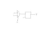
See the circuit. The box is a positive level latch here with clock tied high.

Satisfied with your eagerness.

What is post no. 23? Which document are u talikg of ?
 

Attachments

  • gate.JPG
    gate.JPG
    11.6 KB · Views: 42

It's ..... a single MUX ? That's an excellent circuit to realize case statement. Not casex, though. But thanks for playing.
 

lostinxlation

Look it carefully. It is a mux followed by a positive level latch whose clock input is tied to '1'. So I wrote 'box is a positive level latch here with clock tied high'.

Can u please provide what u are trying to mean by "But thanks for playing. "?

However I still did not get the answer of what you think to realize the circuit in your second question. Can u please let me know? Where is post no 23 to answer your circuit?

We do not find any direct answer from you. You always guide to something else like google, post no. 23 etc to answer your question.

Can you please read the following carefully again and answer me back.I do not find it to be answered in my earlier posts. Does the synthesis tool take care of the properties of casex like even if the case items are unknown it will be able to produce the valid outputs against the case items? If the answer of the above question is true , in that case synthesis tool will have to try to synthesize a gate level netlist that even with 'x' as input will be able to produce either a '0' or '1' in your second question. I need to understand the answer of the above question to underatand what you want to say.

Can u please let me know how casex is realized by synthesis tool to answer your statement "That's an excellent circuit to realize case statement. Not casex, though."
 
Last edited:

Hi lostinxlataion

I am eagerly waiting for your answer and justification for the second question.

Regards
 
Last edited:

Look it carefully. It is a mux followed by a positive level latch whose clock input is tied to '1'. So I wrote 'box is a positive level latch here with clock tied high'.
Latch with triggering pin tied to 1 ? Just a waste of logic, power and space.

I am eagerly waiting for your answer and justification for the second question.
It was answered in my past post.


A sincere response from me is done and no more beyond this point.

After seeing the logic with a mux and a "latch" you provided, my conclusion is that you are trolling.
 
Last edited:

lostinxlation

In post no. 27 you wrote ypou have answered the question in post no. 23. But everybody of us able to see you have not replied it in post no. 23.

Please do not make wrong claims. Can you point out where you have answered this.

We are not trolling. You should leave the habit of blaming people with no grounds. If you do not know try to learn more instead of bleming people.
 

Status
Not open for further replies.

Part and Inventory Search

Welcome to EDABoard.com

Sponsor

Back
Top