Continue to Site

Welcome to EDAboard.com

Welcome to our site! EDAboard.com is an international Electronics Discussion Forum focused on EDA software, circuits, schematics, books, theory, papers, asic, pld, 8051, DSP, Network, RF, Analog Design, PCB, Service Manuals... and a whole lot more! To participate you need to register. Registration is free. Click here to register now.

CJ25-882010 Encoder/Joystick

Status
Not open for further replies.

rfresh737

Newbie level 5
Joined
Mar 11, 2021
Messages
10
Helped
0
Reputation
0
Reaction score
0
Trophy points
1
Activity points
87
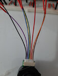
I bought a CJ25-882010 encoder/joystick to control the moving map display of my desktop flight simulator.

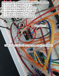
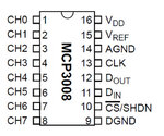
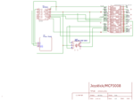
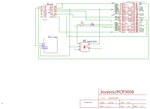
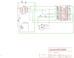
I'm using a Raspberry Pi 4 and have i2c and SPI enabled. I'm using an MCP3008 ADC chip (but I'm not sure if I need it with this encoder?).

The CJ25-882010 spec sheet says voltages for the X Y axis will be from 0 to 5v with 2.5v with the joystick at rest. But when my Python code does a readChannel() on the X and Y pins, I see at rest around 800.

Here are the numbers I see when I move the X Y axis around:

........................X...............................Y
Left...........1023........................1023
Right..............2..........................800
Up.............800.................................2
Down....1023...........................1023

I don't know why I'm not seeing 0 2.5 and 5.0v.

I'm not sure the encoder doesn't have it's own built-in ADC and that I don't need the MCP3008.

I'm a hobbyist programmer (used Ardunios and a Raspberry Pi) and don't have a lot of electrical knowledge.

Thank you for any help at all.

SpecSheetLink
 

Attachments

  • cj25-8.pdf
    112.8 KB · Views: 110
  • Joystick Matrix.jpg
    Joystick Matrix.jpg
    130.9 KB · Views: 105

Hi,

2 LSB means about 0V
1023 LSB means about 5V
800 means about 4V. It should be 2.5V or 512 LSB. This is the only "problematic" value. Please check whether there is a pullup installed or enabled.

Klaus
 

I have not installed any pull up resistors. Which line would I do that with and what res value?

I connected the joystick to 3.3v and I'm getting better results, meaning, the left-right and up-down voltages are now discrete so I should be able to code for specific stick positions. The only problem I see with using 3.3v is that the voltage drops to 0 from about 400 from time to time and that triggers the X Right code to fire. Perhaps a pull up will cure that?

Thank you Klaus
 

Hi,

You should not use pullups.
You should check whether there are pullups enabled by accident. If so switch them off.

Klaus
 

I am not using any pull ups at this time (as far as I know).

I'm using the Raspberry Pi SPI library to connect to the MCP3008. I'm still trying to determine if that library even let's me set a pull up.

I think once I can figure out how to eliminate that random voltage drop to zero (which triggers the left axis if statement in my loop) I'll be ok.

The spec sheet says to use 5v but it works better on 3.3v. I don't know if I'm wiring it up correctly.
 

Hi,

You talk about wiring, but don't show a schematic. How can we know what you are doing?

Klaus
 

I don't know why I'm not seeing 0 2.5 and 5.0v.
You are not reading voltages, you are reading the value returned from the ADC. The MCP3008 is a 10-bit ADC so the values it can return are between 0000000000 and 1111111111 or in decimal 0 to 1023 for 0V and 5V respectively. However, in the middle position, and assuming you are not connecting any resistors to the switch outputs it should produce half the supply to the Joystick (2.5V) which would read as 512 from the ADC.

You should have it wired:
1 - X analog voltage to the ADC
2 - Y analog voltage to the ADC
3 - 5V
4 & 5 - only used if you are using its rotary function, in which case they feed a quadrature decoder
6 & 7 - the 'push' switch, they are isolated from other pins so use it digital input with a pull-up or pull-down resistor.
8 - 0V (GND)

Brian.
 

Hi,

You talk about wiring, but don't show a schematic. How can we know what you are doing?

Klaus

Hi Klaus,

Two wiring attachments.
 

Attachments

  • MCP3008 Wiring.jpg
    MCP3008 Wiring.jpg
    208.9 KB · Views: 93
  • Joystick Wiring.jpg
    Joystick Wiring.jpg
    104.9 KB · Views: 101
  • Joystick wiring 2.jpg
    Joystick wiring 2.jpg
    81.4 KB · Views: 101
  • MCP3008.jpg
    MCP3008.jpg
    54.4 KB · Views: 84

You are not reading voltages, you are reading the value returned from the ADC. The MCP3008 is a 10-bit ADC so the values it can return are between 0000000000 and 1111111111 or in decimal 0 to 1023 for 0V and 5V respectively. However, in the middle position, and assuming you are not connecting any resistors to the switch outputs it should produce half the supply to the Joystick (2.5V) which would read as 512 from the ADC.

You should have it wired:
1 - X analog voltage to the ADC
2 - Y analog voltage to the ADC
3 - 5V
4 & 5 - only used if you are using its rotary function, in which case they feed a quadrature decoder
6 & 7 - the 'push' switch, they are isolated from other pins so use it digital input with a pull-up or pull-down resistor.
8 - 0V (GND)

Brian.

Hi Brian,

Thanks for that clarification. I'll go back to connecting to 5v.

I do have the rotary encoder connected and it is working fine.

I do have the push switch connected and it is working fine.

I'm just struggling with trying to get the joystick X and Y pins of the whole CJ25-882010 device working.
--- Updated ---

I'm attaching my X Y axis testing results.
 

Attachments

  • 3.3volts.txt
    766 bytes · Views: 78
  • 5volts.txt
    407 bytes · Views: 94
Last edited:

I got it all working OK using 3.3v power. The joystick can now move discretely left/right/up/down. For some reason it cannot do that using 5v.

My last question is: do I need to add those resistors as shown in the wiring spec (see attachment). If I do, exactly how do I run the A and B wiring to incorporate those resistors?

Thank you all for the help...
 

Attachments

  • Joystick Wiring.jpg
    Joystick Wiring.jpg
    104.9 KB · Views: 91

Hi,

You really need to read datasheets. Every professional does. All our knowledge comes from the datasheets.
And you need to keep on the information.
Like using caoacitors at power supply pins.
And yes, you need to use pullups on A and B. Either internally enabled or external ones.

Klaus
 

I'm guessing here because we still don't have a full schematic but I think the MCP3008 is powered from 3.3V. There is nothing wrong with that, the device is rated to work down to 2.7V.

The reason for the strange results is that the supply to the joystick is the 'top' reference voltage to it's internal X and Y switches and the divider that sets center voltage. It is designed to work from 5V but maybe you are lucky and yours still works down to 3.3V. I have never opened one of them up but I imagine the manufacturer specifies the voltage because it uses internal LEDs to operate the optical encoder and at reduced supply they may not be bright enough.

Basically, if your ADC works from 3.3V, its full scale reading with 3.3V analog input will be 1023, if you run the same ADC from 5V, its full scale reading would be 1023 with 5V at its analog input. The numerical value isn't absolute, it is a proportion of the supply. If you want to measure real voltages you have to multiply the value by the size of each possible step voltage the ADC can resolve, in other words 'supply / 2^10' For a 3.3V supply each step will be 0.003222V and for a 5V supply it will be 0.004883V.

When you use 3.3V supply and leave the joystick central you measure roughly 512 which works out to 512*0.003222 ~= 1.65V or half of 3.3V which is correct.
With the joystick powered from 5V but the ADC from 3.3V you would expect a reading of 2.5/0.003222 ~= 776 which is close to what you are seeing.

You have two solutions:
1. run the joystick from 3.3V and hope the optiocal output stays working. You might be lucky.
2. run the joystick from 5V, buffer the output voltage with a dual op-amp then divide it down so 5V becomes 3.3V (10K series and 15K to ground).

What you must not do, is keep running the joystick from 5V and the MCP3008 from 3.3V because feeding it 5V is outside the safe input voltage range. Microchip's absolute maximum rating (the point of no return!) is VDD + 0.6V.

Brian.
 

Brian,

The joystick seems to be working OK at 3.3v so I'm going to stick with that. I cannot run the 3008 at 5v because the Raspberry Pi GPIO pins are only good for 3.3v.

Just for completeness, I'm going to now build a Fritz wiring diagram and will post it next.

Thank you...
--- Updated ---

Attached is my wiring diagram. The Fritzing website is down for maintenance so I used EasyEDA to make the drawing.

They did not have the CJ25-82010 Joystick Encoder in their library, so I had to add two components. But between both of them, all of the pins are represented.

The Raspberry Pi GPIO pins are shown on the right side.
 

Attachments

  • Schematic_Joystick MCP3008_2021-03-12.png
    Schematic_Joystick MCP3008_2021-03-12.png
    31.7 KB · Views: 105
Last edited:

Ah ha...you were right Brian. 3.3v is not enough light to make the encoder work reliably. So I had to connect to 5v and it seems to work 100% of the time now.

So while the encoder now works reliably, the joystick X Y is no longer discrete:

X Left == 1023 and Y also shows 1023.
Y down == 1023 and X also shows 1023.
Thus, I cannot detect left x or y down discreetly. So I'm stuck at this time.

I should add that I have three of these encoders and they all have the same behavior. So it doesn't seem to be a specific encoder issue.

X right and y up are discrete so they are ok.

I've updated my schematic to reflect the new 5v power source and the added 2.2k resistors. Please remember the encoder and joystick in the diagram are shown separately but combined they both show the correct pins.
 

Attachments

  • Schematic_Joystick MCP3008_v2.png
    Schematic_Joystick MCP3008_v2.png
    31.9 KB · Views: 90
Last edited:

ADC has absolute maximum input voltage of Vcc (3.3V in your case) +0.6V. Feeding a higher input voltage to the inputs will possibly damage the ADC.
 

Woooaaahhhhh!

Look at the internal schematic of the encoder on its data sheet. The internal resistors are actually of equal value so at their mid-point you get half the voltage. That's why is measures half of full reading when the X and Y switches are open. BUT when you push the joystick it shorts out one or two of the resistors and can connect 5V directly to pins 1 or 2. With the MCP3008 working from 3.3V it seriously violates it's maximum rating which say no pin must go higher than VDD (=3.3V) by more than 0.6V before damage occurs.

It isn't as straight forward to fix as it first seems but there may be a simple solution if your application allows it. If you divide the X&Y output voltage using two resistors you also unbalance the center voltage from the joystick because you are adding extra resistors across the lower internal resistor. This is why I said to buffer it first then use a potential divider. The buffer essentially gives the same voltage out as goes in but it doesn't load the input pin.

However, the fix may be fairly easy. The joystick can only produce three possible X & Y output voltages, it isn't a proportional control where the amount you push it gives a gradual change in output. I would suggest you try this:

1. run the joystick from 5V and the MCP3008 from 3.3V.
2. from the X joystick output add a 10K resistor before the input pin on the MCP3008.
3. from the input pin on the MCP3008 wire another 15K resistor to VSS(0V or GND).
4. repeat steps 2 and 3 for the Y output.

Those steps will reduce the 5V joystick output to a safe 3.3V level, keeping the electrical aspects happy.
Now change your code so it expects 0, 1023 or some other value for central position. I can't calculate what it will be because the values of the internal resistors have to be known and the data sheet doesn't give any clues. As there will be considerable shift in measurements as you move the joystick it should be safe to say anything less than about 50 meets the low voltage requirement and anything above about 975 meets the high voltage requirement. When you find the center position reading, accept anything between 5% below and 5% above as being 'not pushed'.

Brian.
 

Brian,

My schematics have shown 3.3v going into the MCP3008 at pin 16 VDD and pin 15 VREF. Are you and @FvM saying the 3008 is still getting 5v? (from the X and Y wires coming from the joystick?)

OK Brian, I'm implementing your instructions now.
 
Last edited:

It isn't the VDD and Vref causing the issue, 3.3V is fine to use there.
The problem is when you power the joystick from 5V to get reliable rotary encoding, it lets it send the full 5V to the input pin on the MCP3008. None of the pins on the MCP should ever go above VDD and the absolute maximum before damage could occur is VDD + 0.6V (=3.9V) so 5V is way over the top.

Brian.
 

OK, I implemented your instructions. See version 3 schematic attached.

That seems to have fixed the joystick problems!!

The encoder still works OK.

Well, I can't thank all of you enough. I would have NEVER figured all of that out myself. I bought this joystick/encoder because it had all the features I needed for my Xplane flight simulator instrument panel. The thing was, that it was a 5v device. I guess if it had been a 3.3v device, all of these modifications would not have been necessary.

Thanks again to all of you for your wonderful help!!
 

Attachments

  • Schematic_Joystick MCP3008_v3.png
    Schematic_Joystick MCP3008_v3.png
    33.8 KB · Views: 94

I guess if it had been a 3.3v device, all of these modifications would not have been necessary.
Yes, but it is possible no such device is made. The rotary encoder is a plastic disc with slots in it. Either one LED shines through it on to two sensors or two LEDs independently shine through it on to sensors. The LEDs/sensors are positioned so one gets illuminated before the other, by looking at the output of the sensors it is therefore possible to see which direction it was turned and by how much. The LEDs may need several volts (although usually around 1.8V) to light them sufficiently for the sensor to see enough light.

If you have a ball mouse (the type with a roller underneath but not a red glow) pop it's lid off and you will see how it uses the same kind of sensor to detect the direction and distance the mouse is moved.

Brian.
 
Status
Not open for further replies.

Part and Inventory Search

Welcome to EDABoard.com

Sponsor

Back
Top