Continue to Site

Welcome to EDAboard.com

Welcome to our site! EDAboard.com is an international Electronics Discussion Forum focused on EDA software, circuits, schematics, books, theory, papers, asic, pld, 8051, DSP, Network, RF, Analog Design, PCB, Service Manuals... and a whole lot more! To participate you need to register. Registration is free. Click here to register now.

Circuits for high voltage to ADC reading. Problem with simple voltage divider

Status
Not open for further replies.

cartman007

Member level 2
Member level 2
Joined
Nov 13, 2012
Messages
45
Helped
0
Reputation
0
Reaction score
0
Trophy points
1,286
Visit site
Activity points
1,638
Hey Guys

I need to be able to read voltage readings from 9V - 20V and from 70V - 140V with a Atmega 168 5V ADC input.

Now ive tried the simple resistor divider but because im a really cautious person, I really do not like the idea of high voltage NOT being isolated from my MCU.
So ive looked at some circuits with Op-Amps. Problem with the Op-Amps is I cant seem to do the math right.

I cant seem to upload pictures cause ive drawn the circuit specifically for you but it seems there is some kind of error : /
So the current Op-Amp circuit has 2 sets of Voltage dividers on each Inverting and Non-Inverting inputs. It also has a resistor on the output as feedback to the Inverting pin.
The Non-Inverting pin's voltage divider will be the Measuring pin and the Inverting Pin will have 5V connected to it.
Hope that is clear enough.
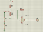
Untitled.png

So my problem is I cant seem to get the Math right!
No matter what I try I keep on getting strange values...Sometimes the output is 5V when the input is at max(140V) and when I go down to 70V it either goes negative or stays roughly the same.

Could someone please give me a trust worthy ADC circuit with the MATH formulas please?

Thanks guys
 

You over complicate it!

The output voltage of that circuit can never go negative because there is no negative voltage supplied to it, however, by biasing the + (non-inverting) input at half supply voltage, you have offset the output by 2.5V even when there is no input voltage. I think you are mistaking voltages below 2.5V as being negative. However, you also use positve feedback through R1 which will make the circuit unstable, it will tend to latch it's output high and abrubtly go low as the input voltage changes.

What you really need is a unity gain buffer. You want to divide the voltage to the correct range (presumably 0V to 5V) for the ADC without the ADC itself influencing the division ratio and you also want to let the ADC input see a low resistance so it can sample as quickly and accurately as posible. A unit gain buffer will do that, just tie the output pin to the inverting input (- input), and use R4/R5 to scale the maximum voltage to 5V at the + input. You do not need a feedback resistor R1.


Brian.
 

That seems to over complicate things. From your resistive voltage divider take a capacitor down to earth to bypass any high voltage pulses, then use two diodes connected to this point one cathode to +5V, one anode to earth. This will constrain your input between +5.8 and -.8 of a volt.
Frank
 

This sounds awesome Brian!

Ok I will add a circuit in a couple of minutes to have a little debate on it!
By the way is there a specific Op-Amp that you would suggest for this application?

Thanks Brian!
 

Any op-amp that will run from a 5V supply and has rail-to-rail outputs will work. If you have a split (positive and negative) supply it opens up far more options but you ideally should add some protection to the ADC input if you do that. A split supply presents the risk that any negative input (including interference) may result in a negative output and that could damage the ADC. It's easy to add protection though, just connect a resistor of say 100 Ohms in series with the ADC input and also add a small schottky diode (BAT85 for example) from the ADC input to ground, anode side to ground. That will protect the ADC from voltages greater than about -0.3V which it should survive safely.

The rail-to-rail output is important, it means the output pin voltage of the op-amp can go all the way down to zero and all the way up to the supply voltage. Many op-amps can't manage to reach the rails and stop short. That would mean you couldn't measure the lowest and highest voltages correctly. The split supply helps to overcome the problem by giving the op-amp more supply voltage so even if it can't reach the rails, it can still cover the voltage range you are interested in. It's a trade off between power supply complexity and op-amp cost. In many designs there are already positive and negative supplies present so it's a no brainer, if you only have a single supply it would be easiest to use a rail-to-rail op-amp.

The LF442 is not rail-to rail incidentally so unless you had an alternative power supply it would not work properly. There are many types that would work, you best bet is to search for the term 'rail to rail op amp' and see what comes up and where you might be able to buy one near your locality.

Brian.
 

Ok lets say I want to use 40V-60V.

Problem I have though is that on 60V using a Voltage divider of 22kOhm and 2kOhm the output will be 5V and that perfect.

But when I get to 40V the ouptut is not 0V or anywhere near, instead it sits at 3.3V .

So I can work with this but it means that im cutting a HUGE chunk of my resolution away that I need to be able to work with?

Anybody got any ideas on how I will be able to use the full resolution of 10bit ADC going from 60V-40V and a 5V input?

Thanks
 

If that is with the LF442 it is explained in my previous reply. The LF442 is not rail-to-rail so what you are seeing is it's output going as close to zero as it can manage. On non-rail-to-rail amps there will be a limit to how close to zero and the supply rail the output can swing so you have to supply it from a higher voltage to ensure it's highest output voltage is still far enough below the supply and a negative supply so it's output can go down to zero with headroom (footroom?) to go toward a negative output.

Options:
1. keep the LF442 but run it from split rails, say +/- 12V so it has plenty of positive overhead and zero output is middle of it's range.
2. change to an alternative op-amp that can swing it's output from zero to positive supply rail.

Brian.
 

Ok lets say I want to use 40V-60V.
.........................................
Anybody got any ideas on how I will be able to use the full resolution of 10bit ADC going from 60V-40V and a 5V input?
For that you have to use an offset circuit like you showed in your first post but reverse the plus and minus input to the op amp.
The circuit you show has positive feedback which will cause the circuit to latch up.

For accurate measurements you need to use a stable voltage reference circuit (not the 5V supply) for the offset voltage and a low offset op amp.
 

You can use also a circuit like the following one. The idea is to divide the input voltage by 8 with a voltage divider. The 5V should be fix. What the circuit is doing is subtracting the incoming voltage (divided by 8) with 5 v and multiplying the result with 2 (gain). So in case of 40 volts you have 40/8=5V input and the result is (5-5)*2=0, in case of 60 volts you have 60/8=7.5 and the final result is (7.5-5)*2=5V.Untitled.jpg
 

    V

    Points: 2
    Helpful Answer Positive Rating
Status
Not open for further replies.

Part and Inventory Search

Welcome to EDABoard.com

Sponsor

Back
Top