carlos.acs.martinez
Newbie level 2
analog input circuit
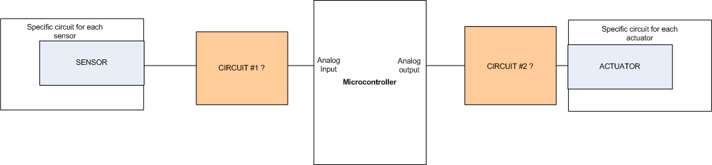
Hi all, I would want to know if there is neccessary to have some kind of electric circuit after the output of an analog sensor (doesn't matter which one) to connect to an analog input of a microcontroller (some amplifier or something else)
The idea is to have a "master circuit" (circuit#1) to connect any output of a sensor to an analog input of a microcontroller, inside the microcontroller is where I would do the A/D conversion.
I have in mind that every sensor would need some specific circuit, but this would be before connecting the circuit that I'm requesting for.
I also would wanted to know if there is neccessary another circuit (circuit #2) between the analog output of the microcontroller and an actuator (doesn't matter which one), to activate any actuator of the market.
The input and the output are not related.
Thank you in advance!")
Hi all, I would want to know if there is neccessary to have some kind of electric circuit after the output of an analog sensor (doesn't matter which one) to connect to an analog input of a microcontroller (some amplifier or something else)
The idea is to have a "master circuit" (circuit#1) to connect any output of a sensor to an analog input of a microcontroller, inside the microcontroller is where I would do the A/D conversion.
I have in mind that every sensor would need some specific circuit, but this would be before connecting the circuit that I'm requesting for.
I also would wanted to know if there is neccessary another circuit (circuit #2) between the analog output of the microcontroller and an actuator (doesn't matter which one), to activate any actuator of the market.
The input and the output are not related.
Thank you in advance!