neazoi
Advanced Member level 6
Circuit to display contents of eprom or PIC memory?
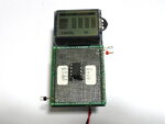
Is there such a circuit that will be able to display the contents of an eprom or PIC memory in hex or bin etc in an array of 7 segment displays? Have you ever seen such a circuit?
I think some old expensive programmers had this feature and they were also able to program the flash without using a computer.
Last edited:
")