Continue to Site

Welcome to EDAboard.com

Welcome to our site! EDAboard.com is an international Electronics Discussion Forum focused on EDA software, circuits, schematics, books, theory, papers, asic, pld, 8051, DSP, Network, RF, Analog Design, PCB, Service Manuals... and a whole lot more! To participate you need to register. Registration is free. Click here to register now.

Circuit to Convert Pulses from Wind Speed Sensor to DC Volts

Status
Not open for further replies.

rahulpsharma

Junior Member level 2
Joined
Apr 4, 2012
Messages
20
Helped
0
Reputation
0
Reaction score
0
Trophy points
1,281
Activity points
1,481
Hello,
I dont wish to use a Microcontroller... (Cos I donno abt it.. :).. ) I just wish to keep it simple but fairly accurate... Following is what I am looking for:

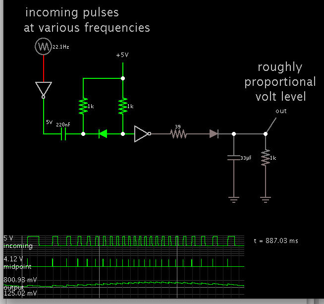
Pulses of varying width will be generated from an optocoupler connected to a Wind Speed Sensor... These pulses needs to be converted using a curcuit to a DC Voltage of, say, 0 - 1V... For low speed, the pulse width will be long and for high speed, pulse width will bee short.... I am planning to have some trim pots to finally calibrate the wind sensor using a reference instrument....!!

Request to kindly help me with some circuit ideas or ICs which can directly convert these pulses to DC Volts...

Regards
 

The function is called f/V-converter, ICs like LM2907 can be used for it. Or simply convert the input pulses to pulses of constant width by a monoflop and average the output pulses in a low-pass filter to get a frequency proportional voltage.
 
The function is called f/V-converter, ICs like LM2907 can be used for it. Or simply convert the input pulses to pulses of constant width by a monoflop and average the output pulses in a low-pass filter to get a frequency proportional voltage.

Thanks... That was helpful... Will try to 'copy' some circuit based on f/v converter.... I checked out the application notes of the IC itself and it had some circuits there... Thanks again..!!
 

For low speed, the pulse width will be long and for high speed, pulse width will bee short

This suggests duty cycle will be the same in all cases.

What will work is to create a pulse of the same length whenever a positive transition occurs. Then to apply these pulses to a capacitor.

The more pulses per second, the greater the charge on the capacitor.

Something like the schematic below:

 
  • Like
Reactions: FvM

    FvM

    Points: 2
    Helpful Answer Positive Rating
What will work is to create a pulse of the same length whenever a positive transition occurs. Then to apply these pulses to a capacitor.

The more pulses per second, the greater the charge on the capacitor.

Something like the schematic below
With the present circuit, this will only work for low input frequencies, respectively output duty cycles << 1. By nature of the circuit, the output duty cycle can't be larger than the input duty cycle, e.g. 0.5. And there will be a rising linearity error, because the capacitor doesn't discharge completely at higher frequency.

A suitable monoflop IC (or 555 in monoflop mode) can achieve linear f/V conversion up to nearly 100 % output duty cycle.

Yes, I saw it becoming non-linear when I tried to get beyond a range of 1:6 or so.

Each charging pulse of 5V can only add an identical increase in charge if the capacitor is far below the level of the charging pulse.

I tried to adjust values so it would look right on a sweep from 10 to 150 pulses per second. This might correspond to a usable range of wind speeds from 5 to 75 mph.

It will need a lot of time spent adjusting values to get better linearity.
 

The function is called f/V-converter, ICs like LM2907 can be used for it. Or simply convert the input pulses to pulses of constant width by a monoflop and average the output pulses in a low-pass filter to get a frequency proportional voltage.
Hi, I was trying to work with a standard circuit based on LM2907 for freq to Voltage conversion... The ckt is available in its datasheet, in Typical Applications (Minimum Component Tachometer) [https://www.emesystems.com/pdfs/parts/LM2907.pdf]... I am trying to replicate the ckt on a breadboard... But as soon as I connect +15V, it drops to almost 0.8V... I checked and re-checked the connections on Breadboard... Changed LM2907, 7815 regulator and even the breadboard.. Still, its the same thing... As soon as I try to connect the power to Pin 5/6 of LM2907, as required by Application Ckt, the DC supply drops to 0.8V, almost...!!

I know I am missing something and it would be difficult for anyone to guess without actually having a look at my breadboard connections... But just trying my luck, if anyone has ever faced a similar problem with LM2907...

Thanks and regards...

- - - Updated - - -

Hi, I was trying to work with a standard circuit based on LM2907 for freq to Voltage conversion... The ckt is available in its datasheet, in Typical Applications (Minimum Component Tachometer) [https://www.emesystems.com/pdfs/parts/LM2907.pdf]... I am trying to replicate the ckt on a breadboard... But as soon as I connect +15V, it drops to almost 0.8V... I checked and re-checked the connections on Breadboard... Changed LM2907, 7815 regulator and even the breadboard.. Still, its the same thing... As soon as I try to connect the power to Pin 5/6 of LM2907, as required by Application Ckt, the DC supply drops to 0.8V, almost...!!

I know I am missing something and it would be difficult for anyone to guess without actually having a look at my breadboard connections... But just trying my luck, if anyone has ever faced a similar problem with LM2907...

Thanks and regards...

I am using a 14 Pin LM2907... In the typical applications, it seems an 8-Pin IC is used... I just rechecked the datasheet and realised this... Does it mean that the Minimum Component Tachometer Ckt which I am trying to replicate on the breadboard, is meant ONLY for 8-Pin Package and not for the 14-Pin IC which I am using...???
 

My LM2907-8 Pin Ckt is still not working.... :(... I am trying to test a freq to voltage converter.... I was trying to implement Figure 6 of the Application Example in the following datasheet of Texas Instruments...
https://www.ti.com/lit/ds/symlink/lm2907-n.pdf

The output is held at 0 for any value of freq input...!!! I am sourcing square wave pulses from a 8051 Micro Controller...!! I am driving a 2N2222 from Microcontroller and switching it between +12V and Ground and the output of 2n2222 is connected to Input Pin 1 of LM2907-8....!!! LM2907-8 is powered by +12VDC...

Also, what is not understood from the example circuit is that the output at Pin 4 of the IC is stated as 67Hz/V.... Since I am trying to make a F to V, I would expect the output to be some volts for some given freq...!! Then why does the datasheet mention the output as Hz/Volts...??

Somewhere in the datasheet it is mentioned that the input pulses must go above and below the ground reference, for the circuit to operate.... Is that true...?? Cos, right now since I am using a Microcontroller to generate the pulses, the pulse train is swinging between 0 and +12VDC... The pulse train isnt going below the ground reference... Can this be a reason for my circuit not working...

Thanks in advance...
Regards
 

I'm not sure if you have read the datasheet thoroughly.

Please take a look at the tachometer input voltage specifications and Figure 5. They clarify that a bipolar input voltage at pin1 is required to overcome the comaparator hysteresis. The reported 0/12V driver won't never achieve it. You can e.g. place a RC high pass before pin 1 that converts the signal into a bipolar one.
 
Status
Not open for further replies.

Part and Inventory Search

Welcome to EDABoard.com

Sponsor

Back
Top