Continue to Site

Welcome to EDAboard.com

Welcome to our site! EDAboard.com is an international Electronics Discussion Forum focused on EDA software, circuits, schematics, books, theory, papers, asic, pld, 8051, DSP, Network, RF, Analog Design, PCB, Service Manuals... and a whole lot more! To participate you need to register. Registration is free. Click here to register now.

Circuit diagram analysis for speaker volume control structure

Status
Not open for further replies.

rajaram04

Advanced Member level 3
Joined
Jun 17, 2012
Messages
871
Helped
6
Reputation
12
Reaction score
5
Trophy points
1,298
Location
earth
Visit site
Activity points
7,687
Hello sir

A very very very common idea of a circuit i am shoeing here which i gonna design as a base for a digital volume control unit

image 01.JPG

please tell would it work ?

if yes then is there any harm to amplifier unit due to external source as trigger to transistor ??????

What are the changes i ll ve to make then ?

The circuit i am showing is not the one i am designing but it is only an idea , may be i gonna use pnp transistor etc etc . . so please help
 

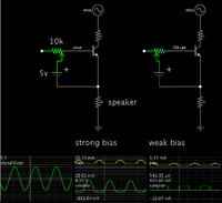
It is only natural to think this would work. It appears to comply with the concepts of transistor gain.

However your schematic will only work during the signal's positive waveform.

Screenshot:


As soon as the signal goes negative, the transistor gain drops.

-----------------------

What about adding a transistor in parallel, to conduct in the opposite direction?

I tried simulating a few combinations of NPN, PNP, orientation, bias direction, etc.
Couldn't find one that works. None seem to provide current flow both ways, as well as smooth gain adjust.

-----------------------

Consider using an FET-based volume control:

https://freecircuitdiagram.com/2012/01/11/voltage-controlled-attenuator-volume-control-using-fet/

Or a photo-resistor:

https://www.instructables.com/id/Make-a-Voltage-Controlled-Resistor-and-Use-It/


kk sir thanks but tell me about first circuit diagram that if i can use a 2k resistor in place of 10 k ??

also tell me about the first link you gave that , is it possible to make it with a bjt ?

Too you told about the "signal goes negative" matter , so how to overcome that ??

Is it possible to design with a photo diode & infra red LED ???????????

please reply
 

Status
Not open for further replies.

Part and Inventory Search

Welcome to EDABoard.com

Sponsor

Back
Top