Continue to Site

Welcome to EDAboard.com

Welcome to our site! EDAboard.com is an international Electronics Discussion Forum focused on EDA software, circuits, schematics, books, theory, papers, asic, pld, 8051, DSP, Network, RF, Analog Design, PCB, Service Manuals... and a whole lot more! To participate you need to register. Registration is free. Click here to register now.

[SOLVED] Choosing Transistor Values for LED matrix.

Status
Not open for further replies.

indignantduck

Newbie level 4
Joined
Aug 16, 2012
Messages
7
Helped
0
Reputation
0
Reaction score
0
Trophy points
1,281
Activity points
1,342
Hi, electronics newbie here;
I'm trying to create a monocolor LED matrix of 11x11 using 74hc595 shift registers.
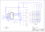
I'm using this schematic I found as a starting point: https://www.edaboard.com/attachment.php?attachmentid=79241&d=1346161224&thumb=1&stc=1

From my understanding, how this works is that you start off with everything disconnected. You send a high signal to the PNPs of each column corresponding to the LEDs you want on. Then you send a high signal to the first row (the NPN transistor). Then, since the LEDs of the first row are connected to ground, the LEDs which have current through them are turned on. Then you disconnect everything, do the same thing for the second row, etc.

I'm having trouble understanding how to calculate the values I need for the transistors. I understand I will need 11 PNP transistors for the anode and 11 NPN transistors for the cathode? Since it is row scanning, in my case, each NPN transistor has to sink up to 11x 20mA (assuming 20mA required to turn on each LED) = 220mA ? Is this right?

Also, each PNP transistor has provide current for 1 LED at a time, so it has to source 20mA? I've been doing a bit of reading online and many sites have been saying that the anode needs to be given 20mA x number of LEDs, but I just don't see why.

So, what values should I be looking for on the transistor data sheet before I go buying them?
Thanks
 

Attachments

  • Serial LED dot matrix driver.png
    Serial LED dot matrix driver.png
    23.5 KB · Views: 573

If you are scanning by rows (rather than columns) then you need to put your current liming resistor in the column (anode) path, otherwise the brightness of the LEDs will vary depending on how many are turned on. Since you are scanning by rows, it's the NPNs that must sink 11x20ma, not the PNPs, as would be the case for column scanning.
 
If you are scanning by rows (rather than columns) then you need to put your current liming resistor in the column (anode) path, otherwise the brightness of the LEDs will vary depending on how many are turned on.
Makes sense!
Since you are scanning by rows, it's the NPNs that must sink 11x20ma, not the PNPs, as would be the case for column scanning.
So the same as what I said? And each PNP needs to source current for 1 LED?
 

I understand I will need 11 PNP transistors for the anode and 11 NPN transistors for the cathode? Since it is row scanning, in my case, each NPN transistor has to sink up to 11x 20mA (assuming 20mA required to turn on each LED) = 220mA ? Is this right?

Also, each PNP transistor has provide current for 1 LED at a time, so it has to source 20mA?
Yes, you got all of that right.

On your circuit diagram, you've drawn the PNP transistors the wrong way around - the emitters should be at the top and the collectors at the bottom. Also, as Barry said, you need to add current-limiting resistors. See pic below.

As for choice of transistors:
The PNP's can be almost any small PNP - whatever's cheapest/most convenient.
For the NPN's it's probably a good idea to use Darlingtons (which have very high current gain).

You can probably save space and money by using transistor arrays. They're ICs specially designed for this sort of thing and contain a number of transistors with all the emitters connected together.

 
You need to define which LEDs you are using 1st. Why? Because the voltage drop increases significantly with current for small LEDs.

Once you have selected your LED, find out the ESR, it will be in the 10~20 Ohm range from the Vf at 10% of the 20 mA rated current from the V-I curve.

Repeat this process for each transistor you select. Vce at desired current then Vce at 10% to get Vf + ESR

Some Bipolar switches have a saturated current gain of 50~5 depending on current and size. Use 10 for now. Darlingtons will have a linear hFE of 10K but a saturated current gain of 100~200.

Once you have this schematic you can see what V+ you need to drive a "common Anode" array with 2 switches 11 LED's.

Allow at about 1 LED voltage drop or less for the current limiting resistor or choose a current source/sink, they take about 2V min.

Example
https://www.digikey.ca/product-detail/en/C503B-RCN-CW0Z0AA1/C503B-RCN-CW0Z0AA1-ND/1922930

**broken link removed**


You can proceed with a discrete design now or consider the constant current source/sink drivers made for LEDs.

5Cd @ 30Deg will be plenty bright is a good choice.
 
Last edited:
You need to define which LEDs you are using 1st. 5V is barely enough for 3 LEDs at 20mA and certainly not 200mA.
He's not connecting any of the LEDs in series. They're single LEDs, not strings.

After figuring out the LED voltage drop and the VCEsat of the transistors, he can calculate what value of current limiting resistors to use. That part is simple.
 
Do I only need the current limiting resistor under the collector of the PNP transistor? (i.e. don't need the 150 ohm resistors in the diagram)
And to work out the Value of the current limiting resistor it is just Vcc - ( VCEsat of PNP at operating condition of 20ma) - (forward voltage of LED) - (VCE sat of NPN at operating conditions of 220mA), then divide this result by 20mA?
Thanks!
 

Do I only need the current limiting resistor under the collector of the PNP transistor? (i.e. don't need the 150 ohm resistors in the diagram)
Yes. Oops, I didn't even notice the 150 Ohm resistors before. You don't need them.

And to work out the Value of the current limiting resistor it is just Vcc - ( VCEsat of PNP at operating condition of 20ma) - (forward voltage of LED) - (VCE sat of NPN at operating conditions of 220mA), then divide this result by 20mA?
That's right. It won't be a very accurate calculation. Just aim for a bit less than 20mA.
 
How do I go about the calculation of the Rb (base resistor ) for the PNPs? This what I think it may be, could totally wrong though.
Vb = Vcc - Vbe.
Then Rb = (Voh - Vb)/Ib
(Ib = Io and V output high are given in 74HC595 datasheet)
And also, the darlington arrays I can connect directly to the 74HC595 since there are already base resistors in the IC?
 

It sounds like you're driving the PNPs and the NPN Darlingtons from 74HC595s. Is that right?

How do I go about the calculation of the Rb (base resistor ) for the PNPs?
They're switched off when the 74HC595 output is high, and switch on when the 74HC595 output is low. If we assume that Vcc = +5V, the transistor's VBEsat = about 0.8V and the 74HC595's output low voltage = about 0.1V, then the voltage across the resistor = about 5 - 0.8 - 0.1 = about 4.1V. The transistor must conduct about 20mA, so a base current of about 2mA would be ideal. R=V/I, so the resistors should be about 2.2K. The exact value isn't critical.

And also, the darlington arrays I can connect directly to the 74HC595 since there are already base resistors in the IC?
I guess so. I don't know what parts you're using but if they have built-in resistors that should be fine.
 
Status
Not open for further replies.

Similar threads

Part and Inventory Search

Welcome to EDABoard.com

Sponsor

Back
Top