Continue to Site

Welcome to EDAboard.com

Welcome to our site! EDAboard.com is an international Electronics Discussion Forum focused on EDA software, circuits, schematics, books, theory, papers, asic, pld, 8051, DSP, Network, RF, Analog Design, PCB, Service Manuals... and a whole lot more! To participate you need to register. Registration is free. Click here to register now.

Choosing clock source for use on PCB

matrixofdynamism

Advanced Member level 2
Joined
Apr 17, 2011
Messages
593
Helped
24
Reputation
48
Reaction score
23
Trophy points
1,298
Activity points
7,681
I am creating my first FPGA PCB. It needs clock source.

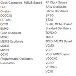
When I went to Mouser website looking for it, it gave me this list of options contained in the image_1 attached.

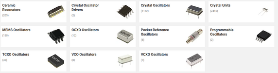
When I went to RS website looking for it, it gave me list of options contained in the image_2 attached.

I am basically completely confused by this plethora of options. I just need a single frequency clock source. The frequency range is 10MHz to 100MHz. This is because I might choose a few different components for this PCB. The PCB is being created for purpose of learning PCB design.

What component am I supposed to look for?
 

Attachments

  • image_1.png
    image_1.png
    9.8 KB · Views: 70
  • image_2.png
    image_2.png
    94.2 KB · Views: 62
If the circuit is digital then a CMOS output "clock in a can"
is my choice. Wide variety of fixed frequencies in the
1-100MHz range.

To go higher you are probably looking at a complex lashup
of reference oscillator, PLL and VCO (w/ filters) to gen and
lock a higher frequency clock by divider feedback (most PLLs
have on-chip counters, but beware the need for even more
"hand holding" if there's registers that need stuffed, etc. -
we had some customers who really liked the simpler,
broadside divider-code pins for lightweight systems).

This latter would also apply to any RF system, where you
must create an accurate reference frequency if you want
channel selectivity and so on. A clean LF clock and a VCO
tuned by a PLL.

Now within just the logic clock ranks, you can find a lot of
variation particularly in tolerances. That's probably the main
thing to know, "how good does it have to be?". Because you
could also make a crude sloppy clock with a hex inverter and
a R and C. If you like crude, sloppy and already there in the
parts bin.
 
Hi,

Honestly, to me it seems you try to find a solution for an unknown problem.
This is like going backwards.

Thus my recommendation: First determine the clock's requirements:
* The FPGA (datasheet) tells you the possible frequency range, but also voltage levels, waveform, maybe even jitter and other specifications
* and your application tells what system clock frequency (maybe range) it needs. Maybe your application even needs several different frequencies. And accuracy of frequency...and so on.

Then - after you have your requirements - you can go for a part search.

Klaus
 
Actually I am creating a PCB for the sake of it i.e learn PCB design. So, there are no actual requirements other than that I must make it as much efficient learning experience as possible.
 

LaTeX Commands Quick-Menu:

Part and Inventory Search

Welcome to EDABoard.com

Sponsor

Back
Top