Continue to Site

Welcome to EDAboard.com

Welcome to our site! EDAboard.com is an international Electronics Discussion Forum focused on EDA software, circuits, schematics, books, theory, papers, asic, pld, 8051, DSP, Network, RF, Analog Design, PCB, Service Manuals... and a whole lot more! To participate you need to register. Registration is free. Click here to register now.

Cheapest Mircocontroller with UART

Status
Not open for further replies.

misnomerfrenzy

Junior Member level 1
Joined
May 15, 2012
Messages
15
Helped
1
Reputation
2
Reaction score
1
Trophy points
1,283
Activity points
1,417
Hello,

Que 1: -

I am building circuit for Water Level Controller. On microcontroller side, my requirement will be to use 3 I/O pins (Low, high and overflow levels of water in tank) and a UART for RS485 communication.

My first choice will be Microchip 12F, 10F controllers. I have browsed through the Microchip search engine to get the microcontroller which will suit my requirement.

Could you help me by suggesting me a cheapest microcontroller which has 3 I/O pins, a UART and possibly an 8 bit timer.


Que 2: -

To choose sensor for Water level controller

I have read various posts related to above topic regarding selection of sensor. I got to know that normal wire, copper rod, steel or iron rod can't be used for long term as they undergo oxidation in water.
I also read that instead of the DC signal, and AC should be used to detect water level.

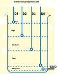
The connection arrangement is similar to that of attached image.

Could you please tell me which are the cheap and long lasting sensors, I should use for this project? Is it necessary to go for AC signal to avoid corrosion of sensor?
 

Attachments

  • water-tank-connections.png
    water-tank-connections.png
    18.4 KB · Views: 69

What baud rate are you planning to use?

I use 10F20x devices for this kind of application. I use the comparator to form a capacitive (AC) sensor so it doesn't have to actually conduct through the water at all and I generate the serial data in software. If you want a more modern device with a capacitive sense module and a UART, I suggest the 12F1822 is a cheap solution. If you are careful, you can use the capacitive sensing method to measure the water depth instead of just checking at fixed levels.

Brian.

Hello,

Please give me a link or document throwing more light on capacitive sensing technique. I searched on google about it in association with water level controller but could not find much.

I am actually thinking to use PIC12F508/12F675 which has 6 I/O out of which 2 I can use as UART by bit banging. But, I dont know, if code memory will allow me to implement UART on I/O s
 

There are application notes on Microchip's web site about capacitive sensing. If you do it on a chip that doesn't have special support, the trick is to use a comparator input and make it into a simple oscillator. Your software reads the comparator output and copies it to one of the port pins, you connect that back to the input of the comparator through a resistor and connect a small capacitor between the input and ground. It will oscillate at a frequency decided by the resistor and capacitor value and you connect insulated probes across it to sense additional capacitance caused by the dielectric between them, ie. the water. You use one of the internal timers to measure the frequency. It doesn't give you a direct measurement of liquid depth but it gives a value proportional to the probe immersion distance.

To bit-bang a serial stream is very easy and you can use any pins, this is the principle:

if you are only sending -
1. Set up a delay routine which is exactly one bit length long (1/baud rate).
2. put the byte you want to send in a register.
3. make the output pin go low for one bit period (make it low, then wait using your delay routine) this is the start bit
4. shift your data one bit to the right so the LSB goes into the carry flag, depending on if 'C' is set or not, make the output pin low or high then wait for one bit period again.
5. repeat step 4 until all the bits have been shifted out
6. make the output high and wait one bit period to make the stop bit.

if you want to receive -
1. set up two delay routines (or one with two selectable delay periods), one should be one bit long as with the receive delay, the other 1.5 bit periods long.
2. look for the input going low, this is the incoming start bit.
3. wait for 1.5 bit periods, at the end of the delay you should be past the start bit and half way through the first data bit.
4. read the bit in and rotate it left into your receive register, then wait one bit period.
5. repeat step 4 until all the bits are received.
6. wait for one bit length and optionally check the input has gone high, this will ensure the final data bit has finished and you are at least some way into the stop bit or idle state.

For true RS485 you will also need a direction control pin.

Brian.
 
@wp100, there is an updated device list on Microchip's web site that allows many of the newer PICs to be programmed by the PicKit 2, that's what I'm using for 1822 devices.

Brian.
 
Hello,

I have searched for the PIC12F1822, if locally available here. But, it is not available. So, I decided to go ahead with PIC16F675. The 3 I/O I will be using for 3 sensors and 3 I/Os for RS485. But, is it possible to implement RS485 on the I/Os? I have never done this before but I have an idea that using bit banging it is possible to implement any 2 wire serial communication. I will be using the internal osc for this PIC and also the Prog. memory available is 1KB.
Any comment on this?

Yes, with 1Kb of memory it is possible to handle the job efficiently..
 
Status
Not open for further replies.

Similar threads

Part and Inventory Search

Welcome to EDABoard.com

Sponsor

Back
Top