Hesambook
Full Member level 2
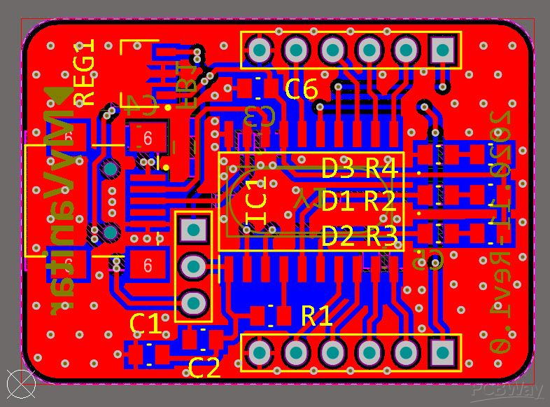
Nowadays USB port is used widely for data transactions between electronic devices and computers. In many scenarios, there is no need to communicate with the USB port directly, therefore electronic designers use USB to UART (RS232-Serial) converter chips, so the USB port is converted to a virtual COM port on the computer. The initial thought of many designers is to use FTDI chips to do the USB to UART conversion. There is nothing wrong with FTDI chips, however, they are expensive. In this article/video, I introduced a cheap USB to UART converter module that uses the MCP2200 chip from Microchip. The converter supports both 3.3V and 5V serial logic levels and uses three LED indicators for power connection, data transmission, and data reception.
The module supports the serial CTS and RTS pins, also six GPIOs that can be used for direct controlling of connected devices. The serial data of the module has been examined and decoded using the UART decoding feature of the Siglent SDS2102X Plus oscilloscope. So let’s get started!


References
Article: https://bit.ly/3q1TzfZ
[1]: MCP2200 datasheet: https://www.mouser.se/datasheet/2/268/22228A-81933.pdf
[2]: RT9166-33GX datashet: https://www.richtek.com/assets/product_file/RT9166=RT9166A/DS9166A-23.pdf
[3]: MCP2200 schematic symbol, PCB footprint, and 3D model: https://componentsearchengine.com/part-view/MCP2200-I/SO/Microchip
[4]: RT9166-33GX schematic symbol, PCB footprint, and 3D model:https://componentsearchengine.com/part-view/RT9166-33GX/RICHTEK
[5]: Electronic designing CAD software plugins: https://www.samacsys.com/library-loader-help
[6]: Altium Designer plugin: https://www.samacsys.com/altium-designer-library-instructions
[7]: Microchip MCP2200 configuration utility: https://ww1.microchip.com/downloads/en/DeviceDoc/MCP2200 Configuration Utility v1.3.1.zip
[8]: Siglent SDS2102X Plus oscilloscope: https://www.siglenteu.com/digital-oscilloscopes/sds2000xp
The module supports the serial CTS and RTS pins, also six GPIOs that can be used for direct controlling of connected devices. The serial data of the module has been examined and decoded using the UART decoding feature of the Siglent SDS2102X Plus oscilloscope. So let’s get started!
References
Article: https://bit.ly/3q1TzfZ
[1]: MCP2200 datasheet: https://www.mouser.se/datasheet/2/268/22228A-81933.pdf
[2]: RT9166-33GX datashet: https://www.richtek.com/assets/product_file/RT9166=RT9166A/DS9166A-23.pdf
[3]: MCP2200 schematic symbol, PCB footprint, and 3D model: https://componentsearchengine.com/part-view/MCP2200-I/SO/Microchip
[4]: RT9166-33GX schematic symbol, PCB footprint, and 3D model:https://componentsearchengine.com/part-view/RT9166-33GX/RICHTEK
[5]: Electronic designing CAD software plugins: https://www.samacsys.com/library-loader-help
[6]: Altium Designer plugin: https://www.samacsys.com/altium-designer-library-instructions
[7]: Microchip MCP2200 configuration utility: https://ww1.microchip.com/downloads/en/DeviceDoc/MCP2200 Configuration Utility v1.3.1.zip
[8]: Siglent SDS2102X Plus oscilloscope: https://www.siglenteu.com/digital-oscilloscopes/sds2000xp