Continue to Site

Welcome to EDAboard.com

Welcome to our site! EDAboard.com is an international Electronics Discussion Forum focused on EDA software, circuits, schematics, books, theory, papers, asic, pld, 8051, DSP, Network, RF, Analog Design, PCB, Service Manuals... and a whole lot more! To participate you need to register. Registration is free. Click here to register now.

Charging and discharging a capacitor using Mosfets (CDI module)

Status
Not open for further replies.

tpb

Newbie level 2
Joined
Sep 12, 2012
Messages
2
Helped
0
Reputation
0
Reaction score
0
Trophy points
1,281
Activity points
1,305
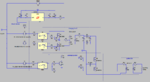
A summary of what the circuit does:
1) takes a 12VDC current, inverts it to a modified sine wave, and transforms it to 300VAC
2) rectifies to 300VDC and charges a capacitor
3) discharges through the ignition coil (something like a transformer)

I'm stuck on step 3. For some reason, I cannot get the capacitor to discharge through the coil using a Mosfet. I've attached a .png of the circuit, and can upload a .asc from LTSpiceIV or link some sources similar to the circuit if it would help.

I've been stuck on this part of the circuit for hours now and don't know what I'm doing wrong, so any help would be greatly appreciated. I'm a bit of a newb when it comes to making real circuits, so any other comments on the circuit would be helpful (most of the values are somewhat arbitrary at the moment).

- - - Updated - - -

It looks like the picture is slightly off from what I got working for steps one and two. The M3 mosfet should be on the other side of the capacitor, otherwise LTSpice shows that it will not charge much beyond 80 volts, if at all. I suppose that makes sense since the drain side should be pulling from the inverter/capacitor.
 

Attachments

  • Capture.PNG
    Capture.PNG
    46.3 KB · Views: 294

An N-mosfet has its gate referenced to the source, which should be the more negative terminal.

It needs to see a definite difference of several volts (give or take) in order for the mosfet to turn on. The way to be certain of this is for the source terminal to be connected to ground.

Your schematic shows a component (transformer) intervening. A voltage will develop across it as soon as the capacitor starts discharging. This is likely to shut off the mosfet.

In some configurations it helps to try a P-mosfet instead.
 

Thanks! That also explains why I could only charge the cap to a certain voltage in some configurations. I'm not sure why I got stuck on that for so long, just guess I didn't know what to look for (or how to use a mosfet).

Would you happen to have any comments on the values chosen for the transformers? I've read that you can simply take the turns ratio and square it for the inductance ratio to simulate, but in some cases the difference in magnitudes seem absurd. Also, does it make sense to model the spark gap as a 1+ meg resistor?

If it all checks out, I'll get to build this before the end of next week.

Thanks again for the help, I've attached a new diagram (a bit messy atm) and the voltage/current at the spark. working.PNGsimSparkPlug.PNG
 

Also, does it make sense to model the spark gap as a 1+ meg resistor?

A spark gap resembles a neon bulb, except its threshold is more like 1,000 V rather than 70 V.

I know of a simulator which contains a model of a spark gap. It's at falstad.com. It's animated and interactive both.

CLick the link below to open the website and load the spark gap simulation (Sawtooth generator). CLick Allow to load the Java applet. It will run on your computer.

The Circuits menu has a couple more spark gap simulations (Tesla coil, Marx generator).

You can alter the circuit by right-clicking on components to bring up an edit window.

https://tinyurl.com/8f63dft

I don't know if you'll want to re-do your entire schematic in Falstad's simulator, however.

Would you happen to have any comments on the values chosen for the transformers? I've read that you can simply take the turns ratio and square it for the inductance ratio to simulate, but in some cases the difference in magnitudes seem absurd.

When you send DC pulses through a transformer, things are not as straightforward as with AC sinewaves.

For your frequency of operation there ought to be a henry value which is most efficient at transferring power from the primary to the secondary.

Use too high a henry value and the result is that primary current is slow to build during On-time. The flux field is weak. The secondary has weak response.

Use too low a henry value and you have start getting inductive saturation during On-time. The flux field becomes stationary. The secondary becomes idle.

Guess it turns out to be a process of trial and error.
 

Status
Not open for further replies.

Part and Inventory Search

Welcome to EDABoard.com

Sponsor

Back
Top