Continue to Site

Welcome to EDAboard.com

Welcome to our site! EDAboard.com is an international Electronics Discussion Forum focused on EDA software, circuits, schematics, books, theory, papers, asic, pld, 8051, DSP, Network, RF, Analog Design, PCB, Service Manuals... and a whole lot more! To participate you need to register. Registration is free. Click here to register now.

charging 2 cell phone batteries

Status
Not open for further replies.

gnomeman

Junior Member level 2
Joined
Nov 2, 2008
Messages
22
Helped
0
Reputation
0
Reaction score
0
Trophy points
1,281
Activity points
1,517
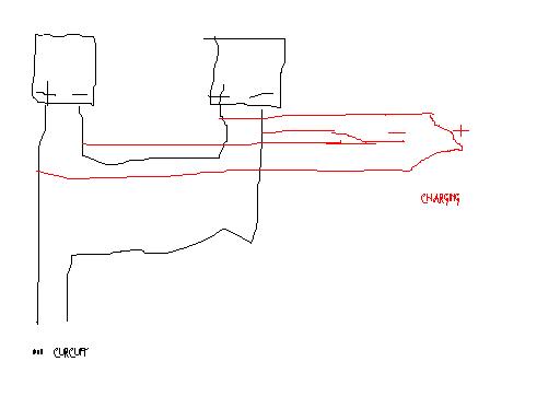
Hi gang, I have a question about charging 2 cell phone batteries with one wall charger.
I have 2 cell phone batteries and the wall charger that is for those batteries. I know that if I connect the 2 batteries in parallel, the charger will fully charge them in about 6 hours.
I want to use the 2 batteries connected in series to power a circuit.
With the series batteries connected to the circuit, can I run wires fron the same batteries to hook them up parallel for charging purposes only?
Will the parallel hookup interfear with the series hookup, will I need to turn off the series when the parallel is used?
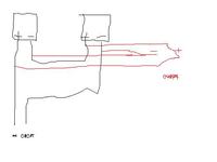
quick diagram attached.
Thanks
Bill
 

hi
oh . be aware that dont do this.
if you connect this circuit to the wall plug it may damage you.
this is only a short circuit that you draw.
you must disconnect both parallel wire before conncecting circuit to the wall plug
at final only one way you must use at same time . series or parallel
 

    gnomeman

    Points: 2
    Helpful Answer Positive Rating
thanks reza17,
The series wires will go to the circuit and the parallel wires will be for charging only.
So what you are saying is I need to put on/off switches in the series wires so that the series wires can be turned off before using the parallel wires for charging. Is this correct?
Thanks again
Bill
 

Batteries charged in parallel become unbalanced with one overcharging and the other not getting a full charge.
It is a good way to destroy both batteries.

Each barrery needs to have its own current regulator and its own charge detector circuit that controls the charging.
 

    gnomeman

    Points: 2
    Helpful Answer Positive Rating
Thanks guys. I appreciate your responses.
Because of your responses to my question, I decided to use a 9 volt battery with a 5 volt regulator for my circuit. It will be a little heavier with the 9v but it shouldn't be a problem. The power is for a reversing and turning circuit for a simple robot.
The circuit will be an object avoidace sensor.
The sensor consists of a simple IR transmitter/receiver, with the output powering an led. The led is inside one end of a black tube, inside the other end of the tube is the sensor for a dark sensing relay circuit.
When the Ir does not see an object, the output is enough to light a white led. The light keeps the relay in the normaly closed position wich in turn keeps the robot moving forward.
When the IR sees an object, the output goes to 0v, the light goes out wich trigers the relay and the robot goes in reverse. When going in reverse, a second motor turns the robot. The IR sensor changes the output at about 5 inches.
I'm in the process of fitting the circuit to the robot. It should work good because I know that the IR and dark sensor work together on a test board.
I'll let you know how the finished robot works out.
Thanks again
Bill
 

I always use a "low dropout" 5V regulator with a 9V battery-powered circuit because an ordinary 7805 regulator needs an input of at least 7.5V but the little 9V battery voltage quickly drops to only 7.2V then the regulator fails.

A low dropout 5V regulator works perfectly when its input drops to only 5.5V.
 

    gnomeman

    Points: 2
    Helpful Answer Positive Rating
what types of battery you are using?
 

audioguru, thanks, thats good to know.
I hooked IR and dark sensor up and used a test motor.
Well, I need to do some debuging.
The IR sensor circuit is doing its job by turning the led on and off but the dark sensor is not reacting to the dark conditions.
I need to go over my wiring but I'm kinda suspecting the problem is my power supply.
The IRcircuit diagram calls for 5v and the dark sensor diagram calls for 6v.
I know that the dark sensor will work fine on 5v.
The reason I suspect the power supply is that I'm using one 9v battery and one 5v regulator to power both circuits. I think maybe the IR sensor is taking some voltage away from the dark sensor and thats why the dark sensor isn't working.
I think I need to have a seperate power supply and regulator for each circuit.

rajudp, I was going to use 2 cell phone batteries but because of what I was told in this forum and because of what I have learned since, I am now going to use 9v batteries and 5v regulators.
Thanks for all your help guys. I'll let you know what I find out with my problem.
Bill
 

You should use a "low dropout" 5V regulator when you use a 9V battery. The minimum input for an ordinary 7805 regulator is 7.5V but a 9V battery quickly drops to 7.2V or less and the ordinary regulator won't regulate.

A low dropout 5V regulator works fine when its input voltage has dropped to 5.5V.

You need only a single regulator.
The little 9V battery might not last long.
 

    gnomeman

    Points: 2
    Helpful Answer Positive Rating
audioguru, The last part of your post you're saying that I can use just one 9v battery and one regulator to power 2 5 volt circuits, is this correct?
If that is what you are saying, then my theory of power loss is not my problem with the dark sensor circuit. The problem must be in my wiring.
I did notice that my 9v battery is getting real warm.
I know that this circuit did work good on the test board so the problem must be in my hard wiring.
Thanks again
Bill
 

A 9V battery gets real warm when its current is much too high maybe because it is shorted. Then it is destroyed.
 

Hi gang. With my circuit problem, I found out that one of my connecting wires had disconnected (not the best at soldering) . Now the circuit works good. Not sure why but the 9v battery is no longer getting warm. Maybe the disconnected wire had something to do with it.
Now I have to hard wire my ir sensor circuit and then mount it on the robot.
When the robot is done, I will post a picture of it here.

Thanks again for all your help.
Bill
 

Status
Not open for further replies.

Similar threads

Part and Inventory Search

Welcome to EDABoard.com

Sponsor

Back
Top