Continue to Site

Welcome to EDAboard.com

Welcome to our site! EDAboard.com is an international Electronics Discussion Forum focused on EDA software, circuits, schematics, books, theory, papers, asic, pld, 8051, DSP, Network, RF, Analog Design, PCB, Service Manuals... and a whole lot more! To participate you need to register. Registration is free. Click here to register now.

[CDC] data transfer between synchronous clocks

Status
Not open for further replies.

giri_lp

Member level 3
Member level 3
Joined
Feb 11, 2006
Messages
61
Helped
0
Reputation
0
Reaction score
0
Trophy points
1,286
Visit site
Activity points
1,657
4 bit wide data bus needs to be transferred into slow clock domain. Sending clock is 100Mhz and receiving clock is 50MHz. The two clocks are synchronous clocks (clocks are derieved from the the same PLL). The 4 bit data changes every write clock cycle.

How to do a CDC without using FIFO?
 

Impossible.

Unless your data is coming in bursts, you've got twice as much data being written in a given amount of time. If it IS in fact in bursts, then a FIFO is the way to go. You'll need to size it according to your burst rate, size, etc.
 
If you can process the data in 8-bit chunks instead of 4-bit chunks in the 50 MHz domain, then you could acquire two 4-bit data in the 100 MHz domain and output an 8-bit value every other 100 MHz clock cycle (i.e. at 50 MHz).
 
Thanks barry


If you can process the data in 8-bit chunks instead of 4-bit chunks in the 50 MHz domain, then you could acquire two 4-bit data in the 100 MHz domain and output an 8-bit value every other 100 MHz clock cycle (i.e. at 50 MHz).

Thanks ads-ee, can you give a hint for the logic involved?
 

How about some timing diagrams? You can figure out the HDL from that.

Code:
//           ___     ___     ___  
//  50 MHz _|   |___|   |___|   |_
//           _   _   _   _   _   _
// 100 MHz _| |_| |_| |_| |_| |_| 
//             ___     ___     ___
// 50_high ___|   |___|   |___|   (sampled on falling edge of 100 MHz)
//           ___     ___     ___  
// 50phase _|   |___|   |___|   |_
//         _ ___ ___ ___ ___ ___ _
//  nibble _|a1_|b1_|a2_|b2_|a3_|_
//         _____ _______ _______ _
//       a _a0__|___a1__|___a2__|_
//         _ _______ _______ _____
//    byte _|__ab0__|__ab1__|_ab2_
//
The key here is you produce a signal that tells you if you are in the high or low phase of the 50 MHz clock in the 100 MHz clock domain. You use that to select which nibble to load in a register that saves that nibble until you receive the next nibble in the other phase of the 50 MHz clock. At that second 100 MHz clock you capture both the saved and the new nibble.

I showed using a falling edge of 100 MHz to capture the 50 MHz phase and another register following that one to align it to the rising edge. I do that to reduce the fan out of the signal that enables each bit of the capture registers (12 loads in total). If you didn't resync it to the rising edge you would be stuck with a signal that only has half the 100 MHz clock period to drive 12 loads, which might not even be a problem at all if the part is fast enough, that is your call.
 
Hi ads-ee,

I am going little slow :(.

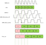
1. Using 100M and 90deg phase shifted 100M clock, alternate nibbles has been sampled
2. using 180 deg phase shifted 100M clock I am able to sample the 8bit data.

Does that makes sense?


timing.png
 

You do know that your 100 MHz clock is shown running at half the frequency of the 50 MHz? Reread my previous post and look at the timing diagram. Your timing ends up with more than one signal being transferred across a half clock cycle.

- - - Updated - - -

Also your diagram shows 0xa getting shifted after the 0xb input shows up? Not exactly sure how you expect to do that.

- - - Updated - - -

Also in post #1 you said you were trying to transfer data from 100MHz to 50MHz, but in post #6 all you refer to is the 100MHz? The 50phase in my example is generated from a flip flop clocked by the 100MHz. It's then used as a clock enable, not as a clock.
 
hi ads-ee,
can we use invert clock from 50Mhz to capture 4bit and normal one to capture 4bit and full 8-bit is clocked by 50MHZ-270degree ?
 

Status
Not open for further replies.

Part and Inventory Search

Welcome to EDABoard.com

Sponsor

Back
Top