Continue to Site

Welcome to EDAboard.com

Welcome to our site! EDAboard.com is an international Electronics Discussion Forum focused on EDA software, circuits, schematics, books, theory, papers, asic, pld, 8051, DSP, Network, RF, Analog Design, PCB, Service Manuals... and a whole lot more! To participate you need to register. Registration is free. Click here to register now.

cascaded amplifier ouput swing problem

Status
Not open for further replies.

hamid159

Full Member level 3
Joined
Aug 25, 2013
Messages
176
Helped
14
Reputation
28
Reaction score
14
Trophy points
1,298
Location
Lahore
Activity points
2,488
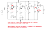
Hy guyz,i have to make an amplifier with a gain of greater than or equal to 300 with output maximum swing of greater than or equal to 10V.
i have tried it with four stages of common emitter.i was able to attain 300 gain but output swing was very low i.e, about 1V.please help me.
how to increase the output swing?
 

Increase R3 to about 10K and bypass R5 with a 470uF capacitor.

(I'm kind of guessing here, since I can't see your circuit)
 
this is circuit diagram
 

Attachments

  • cascaded common emitter amplifier.bmp
    88.9 KB · Views: 115

Q4 is not biased properly for a high output swing. It is almost saturated.
The 600 ohm load is overloading Q4 that has a 2000 ohm collector resistor. Use a load of 3.9k ohms.

Bias Q4 so that its collector voltage is about +3V then it can swing up to +10.5V and swing down to -5V without a load.
Use a load (3.9k ohms) that is much more than the collector resistor.
 

Attachments

  • transistor amplifier.png
    transistor amplifier.png
    20.4 KB · Views: 191
Last edited:
The circuit can be easily changed to give e.g. 10 Vpp output into 600 ohm by adjusting the resistors in the output stage. But before you start, you would fix the circuit specification.

If low quiescent current is an objective, you would go for a class AB complementary output stage.
 

Thank You very much Audioguru and FvM.i have changed load resistance with 3.9k but how to make the collector voltage to be +3V.what should be the current flowing through Rc4?

- - - Updated - - -

Hy FvM,i have also tried class AB output stage but the result no more deviates.This is my class ab output stage circuit.
 

Attachments

  • class ab.bmp
    21.9 KB · Views: 118

The current of Rc4 should be equal to 5.5mA (15-4/2k)
I have the collector voltage at +3V so with the 2k collector resistor, a 3.9k load and a 3.8Vp-p input its undistorted output swing is 10Vp-p which is what is needed.
The collector current is 6.0mA.
 
but Audioguru,output swing is still about 1.1V.

- - - Updated - - -

i've attached the ouput graph according to which maximum ouput swing with 3.9k load is about 1.1V
 

Attachments

  • OUTPUTSWING.zip
    22.2 KB · Views: 104

One side clipping of a waveform primarly suggests an unsuitable bias point rather than missing voltage swing.
 
but Audioguru,output swing is still about 1.1V.
i've attached the ouput graph according to which maximum ouput swing with 3.9k load is about 1.1V
The 3.9k load is supposed to go to ground and be capacitive-coupled to Q4 so how can its voltage swing above the 15V positive supply??
Did you connect the 3.9k load to +15V instead of to ground?

I told you that you had Q4 biased wrong so it was almost saturated then of course its voltage swing is small. Your collector is about -4V but my collector is about +3V. I changed the collector voltage by changing your 18k bias resistor to 10k.
 
Thank you very much Audioguru.....

- - - Updated - - -

i've to use class ab output stage.so i'm replacing RL by class ab output stage.Please verify the circuit for the quiscent current of 10mA and output swing of 10Vp-p with load resistance of 10 ohm.
 

Attachments

  • output stage.bmp
    17.3 KB · Views: 100

The input of your class-AB output stage must come from the collector of an NPN transistor (maybe Q4 in your preamp?) then this output stage replaces resistor RC4.
The value of RE4 must be reduced.
Usually a class-AB output stage uses negative feedback to set its DC operating point and reduce distortion but your circuit has no negative feedback so its DC operating point will be anything.

When the output of your class-AB output stage is +5V into the 10 ohm load the collector current of its Q2 is 500mA. The minimum current gain of a TIP41 transistor at 500mA is about 25 then the base current of must be 500mA/25= 20mA. When the output is at +5V then the base of Q2 will be as high as +6V then if R5 is 680 ohms its current will be (15V - 6V)/680 ohms= 13.2mA which is not enough for some TIP41 output transistors (20mA is needed).

Transistors are all different. Then the base-emitter voltage of Q1 will probably not be slightly less than Q2 or Q3 so the quiscent current could be almost zero or be fairly high instead of the 10mA that you want. Then usually R1 or R2 is a trimpot to adjust it.
 
how much RE4 should be reduced?and how i can use negative feedback in my circuit?i calculate the input resistance of output stage it comes to be about 600 ohm which is much smaller than RC4.so it will affect the voltage gain.am i right?if yes then output swing will also reduce then what should i do?
 

how much RE4 should be reduced?and how i can use negative feedback in my circuit?
Google shows thousands of class-AB amplifier circuits. Most do not use RE so their maximum output swing is as high as possible. ALL audio amplifiers use negative feedback and the thousands of circuits in Google show how. Don't you have a teacher and a text book?

i calculate the input resistance of output stage it comes to be about 600 ohm which is much smaller than RC4.so it will affect the voltage gain.am i right?if yes then output swing will also reduce then what should i do?
Most audio amplifiers "bootstrap" RC4 so its impedance becomes high, Q4 gain becomes high and the output swing becomes high. Bootstrapping allows the collector of Q4 to swing higher than the supply voltage.
 

Status
Not open for further replies.

Similar threads

Part and Inventory Search

Welcome to EDABoard.com

Sponsor

Back
Top