Continue to Site

Welcome to EDAboard.com

Welcome to our site! EDAboard.com is an international Electronics Discussion Forum focused on EDA software, circuits, schematics, books, theory, papers, asic, pld, 8051, DSP, Network, RF, Analog Design, PCB, Service Manuals... and a whole lot more! To participate you need to register. Registration is free. Click here to register now.

Carrier frequency is bound to be 36,38 or 40 kHz.

Status
Not open for further replies.

imranahmed

Advanced Member level 3
Joined
Dec 4, 2011
Messages
817
Helped
3
Reputation
6
Reaction score
3
Trophy points
1,298
Location
Karachi,Pakistan
Activity points
6,492
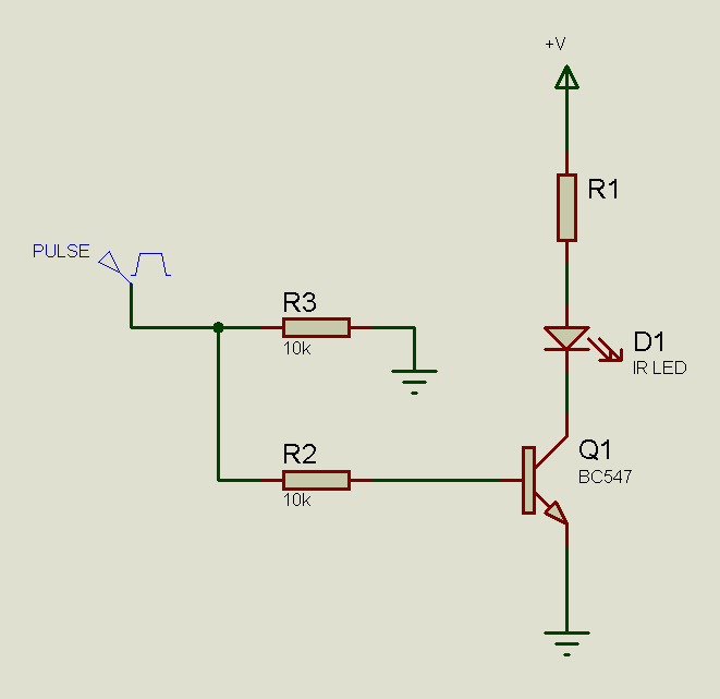
Please let me know that if want to make IR transmitter the carrier frequency must be accurately 36,38,40 kHz or 36kHz to 40kHz and what is the effect of change of carrier frequency in transmit range.
How the carrier frequency change the transmission range?
 

Read the datasheet for the receiver chip/device that you are using.

Typically 2kHz error will give about half the range for a 3 pin receiver.

If half the range is acceptable, then a 38 kHz 3-pin receiver may well work fairly well with a big range of Infrared remote control handsets.

If maximum range is important, then match the transmit carrier frequency to the receiver carrier frequency.
 
How the carrier frequency change the transmission range?

Mismatch of frequency - between transmission carrier frequency and frequency receiver was intended for - reduces the transmission range.

If you want to maximize range, you should also look at other factors such as the IR LED range (check datasheet of the LED) and the current with which the LED is driven.
 
I have a receiver TSOP1756 its carrier frequency is 56kHz,if I make a transmitter of 56kHz carrier,will it cover maximum range?
Do you have any IR transmitter link or hints by using PIC12F683.
 

Last edited:
This attached simple circuit, collector at 56kHz carrier and base at low frequency signal.I want to know that is this circuit is right for transmitting IR signal ,in circuit I will connect IR LED with resistor.
 

Attachments

  • MOD.bmp
    2.3 MB · Views: 57

You can just connect collector to a fixed DC voltage (eg +5V) through the LED and current-limiting resistor (LED and resistor between +5V and transistor collector). You can drive the base directly with the high frequency.
 

Let's take SIRC as example. You can check the protocol here: https://www.sbprojects.com/knowledge/ir/sirc.php

5898412000_1353783410.gif


To send a logical '1' followed by a logical '0':

First send logical '1':
Keep on sending the 40kHz pulses for 1.2ms. Then don't send anything for 0.6ms.

Then send logical '0':
Keep on sending the 40kHz pulses for 0.6ms. Then don't send anything for 0.6ms.

Of course, there are other ways of sending the pulses. I've shown one. You can adapt the concept and technique for the protocol and frequency required.

Hope this helps.
Tahmid.
 
Last edited:

Its ok but i have to know about transistor connection.Please see attached DSN file.

- - - Updated - - -

Its ok but i have to know about transistor connection.Please see attached DSN file.
 

Attachments

  • MOD.bmp
    2.3 MB · Views: 52

I am not using any protocol I want to make own protocol but I cannot understand the transistor connection that how carrier and data signal both inject in base of transistor.
 

PIC12F683 is a perfect choice of PIC for IR transmitter as it has a PWM module.

No need to mix the data signal with the carrier frequency, just set the PWM frequency to 56kHZ and turn PWM on for a mark, then off for a space.

Attached is a working mikroC pro project for Sony SIRC12 protocol at 40 kHz.

connect your transistor driver circuit to GP2, which is the PWM output pin for PIC12F683
 

Attachments

  • IRtx683Sony.rar
    15.3 KB · Views: 45
5898412000_1353783410.gif


If you see the above diagram (for SIRC protocol), you can see that you can output PWM signals (at 40kHz for SIRC) for a specified amount of time and just keep the output off for another given time to send a logical '1' or a logical '0'. Which is sent - '0' or '1' - depends (in the case of SIRC) on the time for which the PWM signal was sent. This PWM signal is sent to the base of the transistor that, accordingly, drives the IR LED.

Hope this helps.
Tahmid.
 
By the way, mod.bmp shows a circuit diagram for a constant current generator of about 8mA.

Voltage across the resistor is 0.6 volts (a diode voltage drop), not 3.8 volts. My calculations result in a 12 Ohm resistor giving 50mA constant current.

The circuit that Tahmid posted is much simpler, 3.8 volts across the resistor is about right, and 76 Ohms for R1 might be a reasonable value.

- - - Updated - - -

You may be in luck. I was bored and decided to modify my mikroC pro code for 56kHz transmission. Result attached.

Or maybe it takes all the fun away by me providing you with the working solution?

Receiver code can be found here: http://www.libstock.com/projects/view/43/infrared-tx-rx-samsung-sharp-nec-sony-rc5-rc6-toshiba-ir-easypic7-pic12-mmb18-mmb33-arm

I do not have a 56kHz receiver to test that the solution works, but I reckon that it should do.

I used Sony protocol (but not really Sony protocol, as Sony use 40 kHz) because it is simple and well documented.

I think the code should work with evaluation version of mikroC pro for PIC compiler, as it is under 2k of code.
 

Attachments

  • IRtx683Sony.rar
    26.9 KB · Views: 44
Last edited:
Status
Not open for further replies.

Part and Inventory Search

Welcome to EDABoard.com

Sponsor

Back
Top