Continue to Site

Welcome to EDAboard.com

Welcome to our site! EDAboard.com is an international Electronics Discussion Forum focused on EDA software, circuits, schematics, books, theory, papers, asic, pld, 8051, DSP, Network, RF, Analog Design, PCB, Service Manuals... and a whole lot more! To participate you need to register. Registration is free. Click here to register now.

Capture Audio signal

Status
Not open for further replies.

sgreen

Junior Member level 3
Joined
Nov 15, 2012
Messages
31
Helped
3
Reputation
6
Reaction score
3
Trophy points
1,288
Activity points
1,481
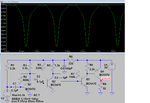
Currently I am working with a circuit that captures audio signal by using a microphone. It gives the amplified output through speaker or headphone. After that I need only analog part that ranges from 1.5-2V (continuously varying). But in the output ac and dc both term are present. DC voltage ranges 2.9-3V.For removing DC Part I am using 10uf electrolytic capacitor between amplified output and target. But it doesn't work. The target is microcontroller ADC input for sampling. As it contains dc it creates a problem. Amplifier circuitView attachment microphone_ckt.bmp is given here. Please help me in this regard.
 

What exactly are you trying to measure with the ADC? Are you sampling several times per audio cycle in order to digitize the audio waveform or are you trying to measure the volume level? Each requires a different solution but just connecting to the ADC through a capacitor will never work.

Brian.
 
  • Like
Reactions: sgreen

    sgreen

    Points: 2
    Helpful Answer Positive Rating
What exactly are you trying to measure with the ADC? Are you sampling several times per audio cycle in order to digitize the audio waveform or are you trying to measure the volume level? Each requires a different solution but just connecting to the ADC through a capacitor will never work.

Brian.

Thanks for reply. I need to sample audio signal through microcontroller and will keep it to a variable which I can display through LCD interface and send this value to my computer through serial communication (USART) for realtime signal monitoring. Whatever, the problem is dc voltage which hampers adc sampling process. How can I remove DC part. Please share naything you know about this.
 

The circuit you found is HORRIBLE!
1) The input impedance of the first transistor is too low so it attenuates the signal from the electret mic.
2) The second and third transistors are biased wrong and are NEVER EVER biased like that! Transistors 2 to 4 do not have any negative feedback so their distortion will be awful.
3) The fourth transistor wrongly puts DC through the earphone which could destroy it.
 

**broken link removed**

about connect to ADC, u can:
1, direct connect to transistor C to ADC input,
2, if you use cap. coupling , then use of a resistor divider
 
  • Like
Reactions: sgreen

    sgreen

    Points: 2
    Helpful Answer Positive Rating
**broken link removed**

about connect to ADC, u can:
1, direct connect to transistor C to ADC input,
2, if you use cap. coupling , then use of a resistor divider

Thanks for reply. But your attachment shows nothing. What do you mean by transistor C. Whatever it will be better for me, if you provide a schematic.
 

The circuit you found is HORRIBLE!
1) The input impedance of the first transistor is too low so it attenuates the signal from the electret mic.
2) The second and third transistors are biased wrong and are NEVER EVER biased like that! Transistors 2 to 4 do not have any negative feedback so their distortion will be awful.
3) The fourth transistor wrongly puts DC through the earphone which could destroy it.

Whatever I have got amplified signal simply in hardware. But my target is to remove dc voltage which creates problem in ADC sampling. If you can, help me in my target.
 

How did you connect the polarity on the electrolytic capacitor that didn't work?

I take capacitor positive terminal to BC558 collector, and negative terminal to ADC input. If it's not possible how can I proceed? My target is only sample the analog signal.
 

The amplifier is horrible but it will work if the transistors are carefully selected, what it doesn't do is cater for variations in transistor parameters and as Audioguru pointed out, it's input and output characteristics are far from ideal.
Your basic problem is that an ADC can't measure negative voltages, meaning any voltage below it's ground pin. If you just remove the DC and leave the AC part behind, half of it will be above and half below ground voltage so at best you will see a rectified measurement (= very high distortion). There are two things you have to do, the first is remove the earphone from the circuit and replace it with a fixed resistor having the same DC resistance. If you leave the earphone connected it will behave like a second microphone and may even cause acoustic feedback, if you simply remove it, the amplifier will no longer work. The second thing is to couple only the audio waveform to the ADC and you correctly assumed a capacitor would do that - however, that brings us back to the +/- problem again. To fix that, you have to apply a fixed offset to the signal, basically 'lifting up' the whole waveform so both it's positive and negative peaks are within the range the ADC can measure. The easiest way to do this is with a potential divider across the ADC reference voltage and ground. If you are using VDD as the high ADC reference and ground as the low reference, all you need is two equal value resistors across the supply pins. You connect the capacitor to the junction of the two resistors and the ADC input. Under no-signal conditions, the ADC should read half FSD, for example if you are using a 5V supply it should read back 2.5V. As the audio adds to the half FSD, it should make the ADC reading increase or decrease according to the audio waveform and that's exactly what you want!

Your next problem will sampling the ADC fast enough but lets cross that bridge when we reach it.

Brian.
 
  • Like
Reactions: FvM

    FvM

    Points: 2
    Helpful Answer Positive Rating
Your next problem will sampling the ADC fast enough but lets cross that bridge when we reach it.
But which bridge the OP is actually heading for?
I need to sample audio signal through microcontroller and will keep it to a variable which I can display through LCD interface and send this value to my computer through serial communication (USART) for realtime signal monitoring.
Besides the confusion about required ADC voltage range, which property of the audio input signal do you want to display? Just level? Then you'll rectify the input signal instead of sampling it directly.
 
  • Like
Reactions: sgreen

    sgreen

    Points: 2
    Helpful Answer Positive Rating
I simulated the horrible circuit. I changed C3 from 10uF to 1uF because it took too long to charge.
The input is a low level sinewave but the output is extremely distorted because the transistors are biased wrong and have no negative feedback.
 

Attachments

  • copy of amplified ear.png
    copy of amplified ear.png
    34.3 KB · Views: 71
  • Like
Reactions: sgreen

    sgreen

    Points: 2
    Helpful Answer Positive Rating
I simulated the horrible circuit. I changed C3 from 10uF to 1uF because it took too long to charge.
The input is a low level sinewave but the output is extremely distorted because the transistors are biased wrong and have no negative feedback.

Would you tell me which software you use to simulate? If you have time, pls share an appropriate schematic of it or tell the way in more detail how smartly I do that. I have failed to design an accurate one. Just help me to make it easy not horrible.
 

My SIM software is the free LTspiceIV from Linear Technology that everybody uses on the other electronics forums.
You need to learn about how to bias transistors peoperly and learn about negative feedback to fix that awful circuit.

THE HORRIBLE CIRCUIT was posted on a website in India as a "spy microphone" circuit by somebody who knows nothing about electronics. It is extremely sensitive but you do not need its very high distortion and its very high sensitivity.
 
  • Like
Reactions: sgreen

    sgreen

    Points: 2
    Helpful Answer Positive Rating
My SIM software is the free LTspiceIV from Linear Technology that everybody uses on the other electronics forums.
You need to learn about how to bias transistors peoperly and learn about negative feedback to fix that awful circuit.

THE HORRIBLE CIRCUIT was posted on a website in India as a "spy microphone" circuit by somebody who knows nothing about electronics. It is extremely sensitive but you do not need its very high distortion and its very high sensitivity.

I have download LTspiceIV from https://www.softpedia.com/dyn-postdownload.php?p=212452&t=0&i=1. Am I right @Audioguru? If not please provide exact link for download your stated software.

- - - Updated - - -

My SIM software is the free LTspiceIV from Linear Technology that everybody uses on the other electronics forums.
You need to learn about how to bias transistors peoperly and learn about negative feedback to fix that awful circuit.

THE HORRIBLE CIRCUIT was posted on a website in India as a "spy microphone" circuit by somebody who knows nothing about electronics. It is extremely sensitive but you do not need its very high distortion and its very high sensitivity.

I have download LTspiceIV from https://www.softpedia.com/dyn-postdownload.php?p=212452&t=0&i=1. Am I right @Audioguru? If not please provide exact link for download your stated software.
 

Instead of downloading software that might be old and full of popups from Softpedia, why not download the latest version (Feb 28, 2013) directly from Linear Technology?
https://ltspice.linear.com/software/LTspiceIV.exe
When you register with them then they will update the software whenever there is an update.

Note that Simulation software shows "typical" transistor spec's. But you cannot buy a "typical" transistor, you get whatever they have which might have low or high current gain.
We design circuits that work perfectly with low, typical or high current gain in its transistors.
 
  • Like
Reactions: sgreen

    sgreen

    Points: 2
    Helpful Answer Positive Rating
Status
Not open for further replies.

Similar threads

Part and Inventory Search

Welcome to EDABoard.com

Sponsor

Back
Top