Continue to Site

Welcome to EDAboard.com

Welcome to our site! EDAboard.com is an international Electronics Discussion Forum focused on EDA software, circuits, schematics, books, theory, papers, asic, pld, 8051, DSP, Network, RF, Analog Design, PCB, Service Manuals... and a whole lot more! To participate you need to register. Registration is free. Click here to register now.

capacitor polarity question

Status
Not open for further replies.

benbiles

Member level 4
Joined
Jan 24, 2014
Messages
76
Helped
0
Reputation
0
Reaction score
0
Trophy points
1,286
Activity points
2,146
I am using some electrolytic 10uF capacitors to hopefully filter DC bias that exists between an ADC and a digitally controlled preamp chip.

PREAMP -> ADC INPUT

The preamp, TI pga2500 sergests using capacitors to decouple the preamp output from the ADC.

The output of the preamp and input of preamp is differential and I have used basic resistor attenuation to match the voltage
swing so the preamp is within the ADC limits..

I'm using Nichicon B1237 6.3V 10uF capacitors. one on each side of the differential audio path with the positive lead attached to
the preamps +1.8v bias.

The AC audio voltage swing is +/-2.4v peek ( not RMS )

There is also +0.9V bias on the ADC side of the differential.

My question is , does anyone know in this case if its essential to have bi-polar capacitors to take out the DC component from both sides?

should I use 2 capacitors back to back with positive leads connected to each bias signal PRE & ADC ?

there's a lot out there on the audiophile forums but I'm more interested in the actual theory of the DC decoupling in this case.

I would like the audio signals to swing around 0V at the point these signals connect together and not use a buffer as recommended by the preamp
datasheet.

Should I also add the bias voltage together with the AC voltage swing to calculate the capacitor rating required ? or in this case the 6.3V is enough?
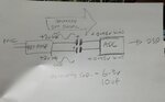
 

Hi,

I'm confused.
----> show a schematic. Hand drawn is O.K. Not from a datasheet, but exactly yours. Complete signal flow and supply voltages and supply capacitors.
Also tell us what ADC you use.

You some times say "from" ADC. Please confirm: signal flow is "to" ADC.

Why do you want to install these capacitors? To get rid of CommonModeVoltage or to get rid of DC in the audio signal?

If it's to get rid of CommonModeVoltage then there is an example schematic in the preamp datasheet, with the capacitors shown in the right place and with polarity information (for the given ADCs).

Also tell us what cut off frequency you expect.

Klaus
 

Traditionally capacitor volt ratings are 'working voltage' meaning it's okay to expose them briefly to peaks slightly higher or lower than their nominal rating. Just as long as the electrochemical dielectric isn't ruined.

Thus you might get away with using one electrolytic. A voltmeter can verify which wire has the higher voltage.

Or else if it really is bipolar AC then use the 2 electrolytics back-to-back trick.

To level shift a signal, it may be sufficient to apply voltage from a supply rail, through a potentiometer.
 

Caps to decouple DC mismatch between preamp and adc?

10uF is the right cutoff, but I may change that. For now I want to be sure there is no DC mismatch or problem. I think the correct name is DC decoupling?

The 8 channel ADC gets very warm, about 55C and I'm thinking it might be working to hard.
--- Updated ---

I think will try 2 caps back to back +- to - + polarity and check that DC is 0v in the middle of the 2 capacitors.
 

Attachments

  • IMG_20210121_165156.jpg
    IMG_20210121_165156.jpg
    1.8 MB · Views: 172
Last edited:

HI,
Caps to decouple DC mismatch between preamp and adc?
This does not answer my question. Mainly common mode DCaudio signal DC ... both are DC between preamp and ADC....

Your schematic. Looks correct. Mainly guessing.
But in detail it depends on the ADC. You still keep it's type as secret...
If a "guessd" answer is not enough .... you know what to do...

Klaus
 

HI,

This does not answer my question. Mainly common mode DCaudio signal DC ... both are DC between preamp and ADC....

Your schematic. Looks correct. Mainly guessing.
But in detail it depends on the ADC. You still keep it's type as secret...
If a "guessd" answer is not enough .... you know what to do...

Klaus

Hi Klaus,

PGA2500 -> 10uF cas --> CS5368

I have PGA2500 VCOM tied to GND

I was following pga2500 datasheet
Figure 8. PGA2500 Analog Output to ADC Analog Input Interface, AC-Coupled

on CS5368 I tried leaving VQ with just caps to GND as in datasheet example.
I also tried VQ with VA/2 = 2.5v with a divider as datasheet says

I am not connecting VCOM ( VQ? ) to VCOM on PGA2500 as its just GND

The CS5368 says it has a digital DC filter

I'm not sure what you mean by, "Mainly common mode DCaudio signal DC ... both are DC between preamp and ADC." ?
isn't all analogue audio AC ? I'm calling the DC part of the audio signal bias , maybe I should be calling common mode audio signal DC ?

I just realised the ADC is running quite hot without the PGA2500 preamp cards slotted into my prototype.
Those cards have the output DC coupling capacitors, so without them the ADC input pins are just floating. ADC still gets very hot.

I stuck a heat sink on the CS5368 and the pink noise that creeps in after time has gone away.
I'll look into a better GND layer for heat dissipation. Maybe it's just my bad pcb layout!

I'll also try capacitors back to back and make sure there is 0V in the middle.

Do you think I should keep VQ on CS5368 at 2.5v ( VA/2 nominal ) as in datasheet ? or just leave it only connected to GND with capacitors?

I'll update here after I have made the changes to the ADC board ground plane and post back here if it worked.
 

G'day Benbiles,

VQ defiantly needs the decoupling caps as shown in the DS. And yes, it could (and probably should) go to your PGA2500 VCOM to set the midpoint of your output to the same reference the CS5368 is using. Now, the datasheet is a little light on the analog design... however, it appears their recommended filter/buffer is DC coupled to the CS5368 inputs using the VQ as the common mode reference. Thus, supplying the required CM offset to the CS5368 analog inputs. The CS5368 DS doesn't detail if the analog inputs are supplied internally with a CM offset... and given you're reading 0.95V at the analog inputs it would seem somethings up. The DS specifies to achieve full range, the peak-peak input must be approx 1 x VA... Therefore... to get max range from a 5Vpp AC signal (typical VA) the analog inputs require 2.5V of CM offset. (we can go 2.5V above and 2.5V below - at the moment you can only go .95V below!). It may also be required to have some form of DC coupling to ensure the bias currents have somewhere to go but, the DS is light. So, provided VQ is connected to VCOM on the PGA, you get rid of the coupling capacitors altogether!! All you really need is a simple RC diff filter for anti-aliasing. Of course if you want to minimise distortion, one should include a propper buffer to match the output of the PGA to the inputs of the CS5368.

EDIT - PGA2500 Datasheet pg14.... exactly what you need! Also note that the PGA2500 requires dual supply rails.

Side note:

The +ve side always goes to the higher potential. If you were to put a DMM across the two points (+ve on your opamp OP and -ve in the adc IP) you would read 1.8V - 0.9V = +0.9V. (infinite impedance DMM of course ;)). However... the values in your schematic seem to contradict your OP. But you get my point.

If the frequency of interest is high enough, (Xc aproaching 0) the coupling cap will only have a smidgen of the AC across it. Therefor your DC bias will be plenty enough to ensure the bipolar isn't reverse biased. At lower freq when Xc increases it would become reverse polerised but likely not cause an issue with the minute currents we're talking about... check the DS most elecrolytics can withstand a certain amount of reverse bias.
 
Last edited:

thanks thunderdantheman for your detailed explanation :)

yes , I had presumed the decoupling caps for VQ are required.

I had not understood CS5368 analogue inputs need to be DC biased in order to function correctly at full voltage swing.

I connected PGA2500 VCOM to VQ and bypassed the decoupling capacitors.

the CS5368 inputs are now +2.8v ( 300mV above PGA2500 max allowed on VCOM input )

VQ / VCOM is 3v ( a bit high ? )

the CS5368 inputs are now 300mV without a pga2500 switched off.

I think the solution here is that I just add the buffer op amps / LP filter circuit to each preamp card as shown in the CS5368 datasheet.

If the inputs to the buffer filter circuit swing around 0v then I guess I could connect PGA2500 VCOM input to 0V

the PGA2500's are running on +/-5V and I can switch them on/off with the microcontroller with optocouplers.

anyay for now the preamps are working gain is louder indicating there is more voltage swing so your theory is correct !

Thanks a lot for the explanation.

next I need to find where the extra 300mV is coming from :)
 

thanks @thunderdantheman for your detailed explanation :)
No problems.. You're in luck.. My day is largely free as I wait on a recompile of an FPGA build that failed last night... so happy to help.

I had not understood CS5368 analogue inputs need to be DC biased in order to function correctly at full voltage swing.

It would help if the datasheet were a little more explicit.

I connected PGA2500 VCOM to VQ and bypassed the decoupling capacitors.

Just confirming the VQ -> VCOM connection has the decoupling caps to GND in place. Your above statement isn't totally clear to me.

the CS5368 inputs are now +2.8v ( 300mV above PGA2500 max allowed on VCOM input )
Hmmm... seems a little high, the DS doesn't spec a range but 300mV seems a bit extreme. Couple of things.. the DS says it can source/sink a max of 10uA and has an output impedance of 25k. The PGA2500 doesn't detail the VCOM input directly but does list analog inputs (i'm assuming this means all analog inputs) have an input resistance of 4k6. And this could be the issue. Even more so if you have eight of these PGA2500 running simultaneously all with VCOM connected to VQ. In this case you will need to buffer VQ with a voltage follower. You could try disconnecting VCOM from VQ and drive it with 2.5V from a lab supply or something.

VQ / VCOM is 3v ( a bit high ? )
Yes.. It's outside of the PGA2500 max.. although there is no mention of it in the absolute max. But i think it could be the driver... Disconnect it from VQ and measure it. If VQ goes back to 2.5V and VCOM is floating around 3V it's likely driving VQ.. Hence a buffer as explained above.

the CS5368 inputs are now 300mV without a pga2500 switched off.
Not a great test as it's an odd use case... especially being DC coupled. It's had to say what the PGA2500 connection to the CS538926 looks like with it powered off.. So could certainly be sinking current.

I think the solution here is that I just add the buffer op amps / LP filter circuit to each preamp card as shown in the CS5368 datasheet.
I reckon that would be the best option.. that way you can connect VCOM to GND and AC couple the PGA2500 to the buffer. This will also increase the dynamic range of the PGA2500 as you will have the full +/-5V swing.

If the inputs to the buffer filter circuit swing around 0v then I guess I could connect PGA2500 VCOM input to 0V
Correct.. explained above.

the PGA2500's are running on +/-5V and I can switch them on/off with the microcontroller with optocouplers.
Just need to be carful of odd behaviour when you powerdown one part of a circuit.. With the buffers and AC coupling this will probably be ok.. but ac coupling caps have a tendancy to cause a thump on power up/down.. definatly on single supply (or DC offset) systems and dual supply circuits if the supplies don't come up together.

next I need to find where the extra 300mV is coming from :)

I reckon it's somthing to do with the VQ not having adiquate source/sink capability... that's where I'd be looking first anyway!
 

Hi,

You write: you tried and tried .... but I still don't know "why"

I see no need to get rid of DC at all... and you give no reason.

Let me try in other words: You try to repair a car. I want to help you with this. But I still don't know what's wrong with the car.
Did you simply try to start it? What happend?


Klaus
 

Just confirming the VQ -> VCOM connection has the decoupling caps to GND in place. Your above statement isn't totally clear to me.

Yes, VQ decoupling still there. I meant by 'bypassing' that I just soldered the DC decoupling cap legs together so there 6.3v 10uF decoupling caps are out of circuit.

It's both a combination of lack of detail in the datasheet and me still not that experienced at building analogue circuits.

I just injected 2.5v into PGA2500 VCOM and input on ADC is 2.5V , other ADC channel inputs 2 -> 8 are at 1.6v ( nothing connected to those at the moment )

VQ unconnected is 2.6v ( looks like the PGA2500's VCOM input sinks more current than the ADC VQ can deliver )

I looked at the CS5368 eval board schematic and there just just using resistor dividers to make VA / 2 and not using using VQ in there input filter buffers. suppose there avoiding using VQ buffer.

I mute the DSP when an preamp ADC channel is switched off , so I if there is a nasty bump noise I guess I could delay switching on the channel.

a lot of noise comes in when I inject the 2.5V to Vcom on the PGA so maybe its better to just use voltage dividers locally on the preamp cards.

CS53868 DS doesn't specify a buffer filter op amp.

Do you think OPA1632 would work ok? I'm using it already as a buffer on my balanced audio drivers and they seam pretty good.
--- Updated ---

Hi,

You write: you tried and tried .... but I still don't know "why"

I see no need to get rid of DC at all... and you give no reason.

Let me try in other words: You try to repair a car. I want to help you with this. But I still don't know what's wrong with the car.
Did you simply try to start it? What happend?


Klaus

Yes , the DC stays. I was not understanding that the ADC requires the AC audio inputs to be biased by half is analogue power rail of 5V.

The car was only driving on 2 wheels and the driver didn't notice :)
 
Last edited:

resistor voltage dividers suffer from poor PSRR.. but then routing your VQ line all round the board to all the other channels has its own problems..
A general purpose opamp rather than your full diff would be better for buffering VQ.. but if its all you have you might be able to configure it as a voltage follower and terminate the -ve output into 10k or something.. the ds doesn't detail a buffer for VQ rather it specifies the output charertristcs.. leaving it up to the designer to decide.
 

resistor voltage dividers suffer from poor PSRR.. but then routing your VQ line all round the board to all the other channels has its own problems..
A general purpose opamp rather than your full diff would be better for buffering VQ..

was meaning do you think the differential op amp would work well for the main audio buffer/filter to the ADC?

how about TLV6001 to buffer VQ? only have 4 channel version.. maybe I can dead bug one onto the ADC board and just see if its noisey or not!

It would be nice if I could voltage follow VQ for all 8 PGA VCOM inputs with one op amp.

who knows what will happen to VCOM on the PGA's in power off state though! mmm.
 

The diff amp could work provided you bias the inputs so you have +1/2 VA offset on both the outputs.. This will be a bit tricky since the diff amp runs a dual supply you would have to put -VQ on the inverting input so as to setup the correct single rail bias for the CS. (As described above). It's not really the intended operation for OPA1632 and will likely degrade the high spec low noise features. You could apply the buffered VQ to the CS inputs (via resistor splitter.. this would affect your input impedace) and capcitivly couple the proceeding bipolar AC stages... that could be an option.

The TLV6001 should do the trick no problems.. and would happily drive all eight channels together.. but a few things to note... you're using some you-beaut low noise parts (PGA2500 and OPA1632 are very low noise) you will undo all of this using the TLV6001.. However it will work and will be fine for testing but something to keep in mind. It might be worth using the TLV6001 to implement the buffer filter shown on the CS datasheet.. that will use two of the four op-amps, and use the third for VQ. Also... if you are looking for low distortion.. rail to rail opamps running their full dynamic range aren't great..

I think I'm getting just as excited as you to see this thing work!
 

Hi,

"Getting warm" and some voltage readings tell me that there's something wrong with your circuit.
I guess the biggest problem is not "signal DC decoupling".

You are free to post your complete schematic and PCB layout...

Klaus
 

Ohhhh Klaussss.... Ol'mate Benbiles is having a better crack than most... there are many ways to skin a cat.. op-amps have more quirks than most other components... I still get bitten by them!! But........
Come'on Benbiles... is it working yet?
 

Ohhhh Klaussss.... Ol'mate Benbiles is having a better crack than most... there are many ways to skin a cat.. op-amps have more quirks than most other components... I still get bitten by them!! But........
Come'on Benbiles... is it working yet?
sorry , I just realised I never replied to this !!!! Thank you Klaussss and thunderdantheman for your help on this.

It's finally all working. I now have the 8 channel ADC and DAC VQ buffered to the preamps / line drivers and HP driver cards.

I have ADC and DAC VQ's biasing OPA1367 differential op amps as buffers now and use 10uF DC filter caps to remove that bias to PGA2500's or and balanced line drivers etc. The reason for this was so I could add the required low pass filter for the ADC and DAC's to filter out any potential harmonic noise coming down from 6mhz. There is also an advantage of using the full dynamic range of the +/-5v of the PGA2500's rather than biasing those directly for the mid point. OPA1367 are great for what I'm making since there low power and don't produce to much heat.

the preamp cards are using stupid 1.27mm headers and I need to make them edge card or come up with another stackable solution eventually.


7759771633526507945.jpg
 

Status
Not open for further replies.

Similar threads

Part and Inventory Search

Welcome to EDABoard.com

Sponsor

Back
Top