Continue to Site

Welcome to EDAboard.com

Welcome to our site! EDAboard.com is an international Electronics Discussion Forum focused on EDA software, circuits, schematics, books, theory, papers, asic, pld, 8051, DSP, Network, RF, Analog Design, PCB, Service Manuals... and a whole lot more! To participate you need to register. Registration is free. Click here to register now.

Capacitor Bank Charging Through Mains

Status
Not open for further replies.

SACHIN C

Full Member level 2
Joined
Jul 6, 2013
Messages
143
Helped
4
Reputation
8
Reaction score
4
Trophy points
18
Activity points
1,048
Dear All,
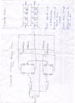
I want to charge capacitor through Mains directly using bridge rectifier diode,so how can i limit the current flowing in capacitor because initially capacitor will act as an short until applied voltage reaches across capacitor?

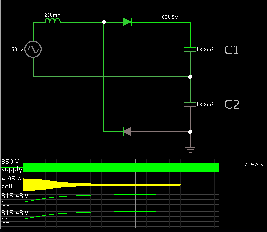
Capacitor Value =4700uF/450VDC each,Likewise 4 Capacitor are connected in parallel which add up to 18,800uF/450VDC.This type of two Bank then connected in series which will again add up to 9400uF/900VDC.
Basically i want 700VDC across series bank of capacitor,presently resistor used in series but wattage matters,as soon as i switched on the MCB to bypass the resistor so that the required current then can flow to Capacitor via MCB but,it is getting tripped(MCB connected across resistor).

Resistor across capacitor bank viz.680K/0.25W used for voltage balancing,

Thanks & waiting for knowledge enhancement,:smile:
 

Attachments

  • Capacitor Bank.jpeg
    Capacitor Bank.jpeg
    711.3 KB · Views: 140

I would be careful with those switches across the output ! They won't last long if you close them with charge on the capacitors and it will be instant death to something if you close them with the mains switched on.

The problem you have is the same as with most SMPS designs, the usual fix is to add a thermistor (surge limiter) in series with the mains connection. It's a resistor that starts with a relatively high value and hence limits the current but in doing so it heats up and it's value drops to allow 'normal' current to flow through it.

Brian.
 

Hi betwixt,
The switches used are MOSFET with PWM Signal to control ON/OFF operation,i thought of Thermistor initially but, it will blow suddenly as capacitor charging MCB switched ON,because the capacitor initially act as short until the appliad voltage reaches across Capacitor Bank?

Actually here capacitor needs continuos charging current untill it reaches to applied voltage,so how surge limiter will work?

Also i observed if we use single Resistor in Phase(Live) path the total voltage gets dropped across resistor,so i used two different resistor?

To limit the current after bypassing resistor say at 640VDC(applied 670VDC),inductor used to limit the current?

Thanks & waiting for knowledge enhancement,:smile:
 
Last edited:

You don't say what current your rectifiers are rated at. If they are rated at 5 A, then you have to limit the input current to them to 5 A, so you need a 230v/5 = 46 ohms. At switch on it will dissipate 5 X 230 = 1150W. As the caps charge at CR the current will have dropped to 60% = 3A, CR = 46 X 4500 X 10^-6~ .2 S, so if the resistor is left in circuit for 1 second the caps would have charged and the resistor could be shorted out. So the resistor that was dissipating 1 .1 kW, is now dissipating 0 W!. So providing a robust and large resistor is used it should come to no harm (20W rating?). So now you need some thing to short out the resistor. 230 V power transistor transistor could be used, but at the point of the transistor going short, there could still be a short but high duration of current though it, so it should be a power transistor. I would go for a high voltage low current relay with 5 A contacts. The coil I would feed from the capacitor voltage via a string of zener diodes and resistors so the relay pulled it at 90% of the expected DC output voltage. For a safety measure I would put a 100 degree thermal fuse near the resistor so if the relay did not short it out and it got too hot (and cause a fire) the fuse would blow and break the input voltage.
Frank
 

Hi chuckey,
Presently in circuit i have used MCB to bypass the resistor,can it will also work instead of power transistor?


Thanks & waiting for knowledge enhancement,:smile:
 

1.

Your split supply looks okay at first sight, but it will short circuit through two diodes during one half of the cycle.

2.

Your schematic has a coil at the left. The inductive drop method may work for you, when you are drawing a lot of Amperes. The more AC current you draw, the lower the Henry value needs to be.

The winding still needs to have a suitable current rating, of course.
 

chuckey,
The value of resistor is 300ohm/300W,


Thanks & waiting for support to enhance the knowledge,:smile:

- - - Updated - - -

- - - Updated - - -
 

BradtheRad ,
Yes,i observed the same problem of diode shorting,so i connected isolation tranformer in one of the path now it is not getting shorted,
But now also i removed inductor & only resistor,MCB connection introduced will it works?


Thanks & waiting for support to enhance the knowledge,:smile:
 

Two diodes will produce a split supply to your capacitor bank.

A .23 H coil can be added in series, so that current will not go over 5A.

Screenshot:


In 17 seconds the capacitors will charge to 90 percent of the incoming peak V (theoretically).
 

With 300 ohms CR = 300 X 4500 X 10^-6 = 1.35 seconds, So the charging current will be low at 6.5 Seconds. So switch the mains on, after 7 seconds short out the 300 resistor. The current will be limited to 1.3 A (300/230) so the max power will be 300W,but only for less then one second.
Frank
 

Status
Not open for further replies.

Similar threads

Part and Inventory Search

Welcome to EDABoard.com

Sponsor

Back
Top