Continue to Site

Welcome to EDAboard.com

Welcome to our site! EDAboard.com is an international Electronics Discussion Forum focused on EDA software, circuits, schematics, books, theory, papers, asic, pld, 8051, DSP, Network, RF, Analog Design, PCB, Service Manuals... and a whole lot more! To participate you need to register. Registration is free. Click here to register now.

Capacitor at output of opamp

Status
Not open for further replies.

cupoftea

Advanced Member level 5
Joined
Jun 13, 2021
Messages
2,583
Helped
54
Reputation
108
Reaction score
115
Trophy points
63
Activity points
13,560
Hi,
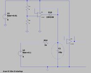
Isnt it strange that you cant have a capacitor of >~100n at an opamp output, but if its an opamp clamp (as attached), then you can have a cap as big as you like.
Why is this?

LTspice also here...

Version 4
SHEET 1 7004 1720
WIRE -3776 -896 -4048 -896
WIRE -3616 -896 -3776 -896
WIRE -3248 -896 -3616 -896
WIRE -3776 -848 -3776 -896
WIRE -3392 -800 -3680 -800
WIRE -3616 -752 -3616 -896
WIRE -4048 -736 -4048 -896
WIRE -3680 -736 -3680 -800
WIRE -3648 -736 -3680 -736
WIRE -3520 -720 -3584 -720
WIRE -3392 -720 -3392 -800
WIRE -3392 -720 -3456 -720
WIRE -3776 -704 -3776 -768
WIRE -3648 -704 -3776 -704
WIRE -3776 -672 -3776 -704
WIRE -4048 -592 -4048 -656
WIRE -3776 -512 -3776 -592
WIRE -3616 -512 -3616 -688
WIRE -3184 -448 -3312 -448
WIRE -3248 -416 -3248 -896
WIRE -3312 -400 -3312 -448
WIRE -3280 -400 -3312 -400
WIRE -3184 -384 -3184 -448
WIRE -3184 -384 -3216 -384
WIRE -3056 -384 -3184 -384
WIRE -3584 -368 -3856 -368
WIRE -3392 -368 -3392 -720
WIRE -3392 -368 -3504 -368
WIRE -3280 -368 -3392 -368
WIRE -3392 -304 -3392 -368
WIRE -3856 -272 -3856 -368
WIRE -3856 -64 -3856 -192
WIRE -3520 -64 -3856 -64
WIRE -3392 -64 -3392 -240
WIRE -3392 -64 -3520 -64
WIRE -3248 -64 -3248 -352
WIRE -3248 -64 -3392 -64
WIRE -3040 -64 -3248 -64
WIRE -3520 -32 -3520 -64
FLAG -3616 -512 0
FLAG -3776 -512 0
FLAG -4048 -592 0
FLAG -3520 -32 0
SYMBOL Opamps\\LT1006 -3248 -448 R0
SYMATTR InstName U23
SYMBOL res -3488 -384 R90
WINDOW 0 0 56 VBottom 2
WINDOW 3 32 56 VTop 2
SYMATTR InstName R54
SYMATTR Value 1k
SYMBOL Opamps\\LT1006 -3616 -784 R0
SYMATTR InstName U25
SYMBOL diode -3456 -736 R90
WINDOW 0 0 32 VBottom 2
WINDOW 3 32 32 VTop 2
SYMATTR InstName D10
SYMATTR Value 1N4148
SYMBOL res -3792 -864 R0
SYMATTR InstName R55
SYMATTR Value 4k
SYMBOL res -3792 -688 R0
SYMATTR InstName R57
SYMATTR Value 1k
SYMBOL cap -3408 -304 R0
SYMATTR InstName C1
SYMATTR Value 10µ
SYMATTR SpiceLine Rser=0.03
SYMBOL voltage -4048 -752 R0
WINDOW 123 0 0 Left 0
WINDOW 39 24 44 Left 2
SYMATTR InstName V1
SYMATTR Value 5
SYMATTR SpiceLine Rser=0.01
SYMBOL voltage -3856 -288 R0
WINDOW 123 0 0 Left 0
WINDOW 39 24 44 Left 2
SYMATTR InstName V2
SYMATTR Value 5
SYMATTR SpiceLine Rser=0.1
TEXT -4082 -8 Left 2 !.tran 0 10m 0 startup
CIRCLE Normal -3312 -160 -3472 -368 2
 

Attachments

  • Cap at opamp output.jpg
    Cap at opamp output.jpg
    77.4 KB · Views: 145

Hi,

with a usual circuit the capacitor is pushed and pulled by the OPAMP and the OPAMP tries to stay in regulation all the time. Every input noise is also driven to the capacitor, causing current.

On the clamp circuit, the capacitor os pulled only and the OPAMP goes out of regulation (at least) half of the time.
Usually you avoid "out of regulation" condition with OPAMPs because of
* distortion
* violating differential input voltage range.
* latch up time
* phase reversal
.. and all the resulting drawbacks.

You need careful OPAMP selection for this clamp circuit .. not to damage the OPAMP and to get the desired results.

Usa a random OPAMP and get disastrous output.

Klaus
 
Thanks, better to use say a 330R resistor from D10 cathode to opamp U25 output?
 

Hi,

The resistor may limit the current, but does not prevent a single of the problems written in post#2.

Klaus
 
Last edited:
Thanks, page 12 of the article kindly given by Dana shows also a cap at opamp output, just with a diode inbetween

there is a fair chance that ckt will latch low at start up ...
...thanks, and we are wondering whether it will latch low and then oscillate?...as you know, an opamp isnt generally allowed to have a cap at its output......and the opamp probably cant "see" the diode between its output and the cap?
 

Hi,
...thanks, and we are wondering whether it will latch low and then oscillate?...as you know, an opamp isnt generally allowed to have a cap at its output......and the opamp probably cant "see" the diode between its output and the cap?
But understand: the capacitor isn´t connected to the output.

Oscillations means "up and down".
When using the circuit of post#1 the capacitor is "conneted" only when the OPAMP output is smaller than the capacitor (diode voltage drop), then the capacitor get´s discharged.
Due to the nature of the capacitor ot will keep it´s voltage, even when the opamp output becomes higher. Then there is no current flow. No current flow, no problem. So due to the "up and down" of the oscillation the oscillation stops itself.

Usually an oscillation means current flow in both directions. This is avoided by the diode.

With a forced AC we just see short current peaks at the negative peaks of the voltage. The most of the time there is no current flow at all.

Klaus
 

Thanks, page 12 of the article kindly given by Dana shows also a cap at opamp output, just with a diode inbetween


...thanks, and we are wondering whether it will latch low and then oscillate?...as you know, an opamp isnt generally allowed to have a cap at its output......and the opamp probably cant "see" the diode between its output and the cap?
There are OpAmps specifically compensated to handle large C loads. This situation
a little unusual, so I simed it, with an LM324 which is not comped for large Cload.
It does not seem to oscillate. That may be the fact that when loop is closed in your
circuit its unity G and that means Rout of OpAmp at its lowest, so its pole/phase
shift occurs at a freq >> GBW.

Regards, Dana.
 

Status
Not open for further replies.

Similar threads

Part and Inventory Search

Welcome to EDABoard.com

Sponsor

Back
Top