Continue to Site

Welcome to EDAboard.com

Welcome to our site! EDAboard.com is an international Electronics Discussion Forum focused on EDA software, circuits, schematics, books, theory, papers, asic, pld, 8051, DSP, Network, RF, Analog Design, PCB, Service Manuals... and a whole lot more! To participate you need to register. Registration is free. Click here to register now.

capacitive transimpedance amplifier for image sensors

Status
Not open for further replies.

VeeJayy

Junior Member level 1
Joined
Jan 13, 2017
Messages
18
Helped
0
Reputation
0
Reaction score
0
Trophy points
1
Activity points
201
Hello,

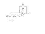
I have attached a picture of the capacitive transimpedance amplifier which is generally used in image sensors. Can anyone help me understand the use of the input capacitor 'Ca'?

I know that the photo diode in itself has a diffusion capacitance which gives a measure of the charge stored with respect to the photons incident on it. But what is the necessity of the additional capacitance Ca here? ctia.png
Thank you
 

Hi,

Where is the circuit from? Please give it´s source.

I expect there is some description.

Klaus
 

Not necessarily any source. Just an assignment from a professor to explain the whole circuit. I found relevant descriptions for every other component but for the input capacitor and hence wanted to know if anyone has any idea about it.
 

Hi,

you should have better listened to what the professor explained....

My idea:
This was never meant as extra capacitor. It just shows the diode´s capacitance.

Klaus
 

Haha he didn't explain. This is sort of an assignment expecting the students to do so.

Anyways, I know that it is mostly just an indication of the equivalent capacitance of the diode. But, in the case that it was an external capacitor connected in parallel to the diode, what would it do? Would it be a good addition? My thoughts

- It would increase the full well capacity of the sensor, but increase the area of the sensor
- The sensitivity of the sensor decreases

Do you think adding a capacitor parallel to the diode, eventually increasing the capacitance at the floating diffusion node be practical or rather a good idea to do so? Just posing this question with a hypothetical assumption that the capacitance is external and not necessarily the diode depletion region capacitance.

Thanks again.

VJ
 

Hi,

as said, I think: This was never meant as extra capacitor.

An extra capacitor
* neither increases the area
* nor decreases sensitivity
of the photodiode.

I don´t think an extra capacitor is useful at all.

Klaus
 

Haha he didn't explain. This is sort of an assignment expecting the students to do so.

Anyways, I know that it is mostly just an indication of the equivalent capacitance of the diode. But, in the case that it was an external capacitor connected in parallel to the diode, what would it do? Would it be a good addition? My thoughts

- It would increase the full well capacity of the sensor, but increase the area of the sensor
- The sensitivity of the sensor decreases

Do you think adding a capacitor parallel to the diode, eventually increasing the capacitance at the floating diffusion node be practical or rather a good idea to do so? Just posing this question with a hypothetical assumption that the capacitance is external and not necessarily the diode depletion region capacitance.

Thanks again.

VJ

Floating diffusion (sense node) capacitance has two components - the p-n junction capacitance, and (parasitic) capacitance of interconnects.
The total capacitance of floating diffusion is decided based on a trade-off between the sensitivity (conversion gain) and the full well capacity, as you correctly stated.
Full well capacity is the property of the photodiode, not floating diffusion, but when that whole well charge is dumped on the sense node - it's voltage should no go negative, otherwise it will be spilling electrons out (not good).
And that will be determined by the product of floating diffusion capacitance and the Vdd.
 
I wasn't mentioning the area of the photo diode. I meant the area of the external readout circuit altogether taking up more area in comparison with the photo diode. It would eventually be a disadvantage since the readout circuit would take more area with an extra capacitor than without, eventually taking up more space in the pixel area which would include both the photosensitive area and the circuit right?

And the sensitivity also was mentioned with respect to the total circuit. Or may be its a parameter i'm yet to understand.
 

Thanks! That helped.

But what do you mean by the whole well charge dumped on the sense node it shouldn't go negative?`

And do you think an external capacitor is somehow necessary at the input terminal to 'not let it go negative'? Would an external capacitor increase the total capacitance at the floating diffusion eventually giving certain benefits to the circuit?

Thanks,
VJ
 

A bit of browsing of SPIE and IEEE periodicals ought to
give you a good idea of ROIC art and then you would know
what (if any) meaning this Ca has. I do not recall seeing
anything of this sort in the unit cell designs I've looked
at. But realism in simulation demands expression of the
input parasitic C that the photodiode does not embody,
because -Cint/Ca is a closed loop gain limit (integration
is the plan, but things are not ideal). And in the final
article there's a ton of overflying routes and bussing
that at minimum need accounting-for.
 

Thanks for the tip. I seemed to have looked up alot of IEEE articles with regard to the same and they dont seem to give a really good explanation regarding the CTIA circuit. Simple questions as to how the feedback capacitor needs to be selected, how the reference voltage needs t be selected and so on. A standard article as such. Most of them seen to give an idea about the working but not regarding how the components are to be chosen and so on. I have browsed more than 30 articles and none seem to give a perfect idea regarding the tradeoffs and the selection of components or voltages for that matter.

It would be great if I could get a heads up in this matter, or may be an article that helped you with this regard or so. It would really help me decode the circuit 100%. Unless I feel theoretically at ease, I just don't feel like i have enough explanation for a professor. :)

Thanks everyone!

VJ
 

Status
Not open for further replies.

Similar threads

Part and Inventory Search

Welcome to EDABoard.com

Sponsor

Back
Top