Continue to Site

Welcome to EDAboard.com

Welcome to our site! EDAboard.com is an international Electronics Discussion Forum focused on EDA software, circuits, schematics, books, theory, papers, asic, pld, 8051, DSP, Network, RF, Analog Design, PCB, Service Manuals... and a whole lot more! To participate you need to register. Registration is free. Click here to register now.

Capacitance Measurement circuit

Status
Not open for further replies.

nanana_1011

Member level 2
Joined
Nov 9, 2014
Messages
50
Helped
0
Reputation
0
Reaction score
0
Trophy points
1,286
Activity points
1,636
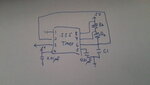
Hello! I am going to make a circuit for measuring the capacitance. I have found many in design which have used the timer. Is there a must for using a timer? I want to know whether there is any other way without the timer.
Thank you!

- - - Updated - - -

I forget to tell that it is used to measure around 1pf to 1000pf.
 

Hi,

how do you want to measure?
What circuit do you use?

What´s wrong with using a timer?

Depending on your circuit ....maybe a f-V converter and input to ADC is a solution without timer.

Klaus
 

I want to convert a differential capacitance to voltage. Finally, I can put it into the analog digital converter and do other process. I have do some search in the internet. I get stuck in the first part. The circuit needs to be accuracy for measuring the pf capacitor. For the timer, it will measure the capacitance by altering frequency but I do not know what the next step is after the output from the timer. I also do not know whether it is accuracy. I dont have any ideas.
 

Please specify "differential capacitance" unambiguously. Does it mean both capacitor terminals have additional arbitrary capacitance to ground that should be eliminated in the measurement? If so, how much capacitance?

There are different methods to measure capacitance like making the capacitance under test part of a LC oscillator (I guess that's what you mean with "altering frequency"), or measuring charge/discharge time with a current source or a load resistor. Also measuring reactive impedance with a AC voltage or current source.
 

There are 2 capacitor. One is fixed for reference and other can be changed. By comparing their difference, I can get information. I would like to compare their capacitance and convert it into voltage. Then I will put it from analog to digital.

In timer 555, the frequency may be 60Hz. With different capacitance, it will change the frequency. Thus, I can get the differential capacitance according to different frequency. But in this method, how do I get the output frequency and convert it into voltage which is same as capacitance to voltage. And then to ADC.

I am going to search a method to convert capacitance to voltage without timer. Also, the input power source is DC voltage.

For example,
Freq Capacitance Voltage
10 1pf 0
15 11pf 1
20 21pf 2
 

Does it work for extremely low capacitance like 0-120pF?
 

Attachments

  • 20141110_151625.jpg
    20141110_151625.jpg
    2.9 MB · Views: 102

Hi,

0pF is really extremely low capacitance.

****

You should find the answer in the 555 datasheet.
I don´t have the 555 circuits in my head, but i think the circuit generates a frequency depending on C.
Then it should work.

****

Klaus
 

I find that the period is related to Ra, Rb and C. If C is very low, the frequency will be very large. And it is easily affected by noise. I would like to find a method to have accurate result.
 

Hi,

can you specify "accurate" (with values)?

Do you really need absolute accuracy, or relative accuracy or just a high resolution.
I ask, because the capacitance range may fit to a capacitive touch sensor, where absolute accuracy is not important.

affected by noise:
This is true. But with this application one does not measure a single cycle time, but one measures the number of pulses within a fixed period. Lets say 100ms.
If you do so, then the jitter (you called it noise) becomes irrelevant. At least for jitter frequencies higher than 10Hz.

****
For sure one can make accurate measurement. I designed a measurement tool for testing piezos (medical imaging).
It has a fixed sinoidal excitation with current and phase shift measurent. It is able to precisely measure down to sub-picofarads with parallel resistive load.
Here the wire length and wire geometry has significant influence on the result. Therfore we do one time calibration with known capacitors and store the calibration values in EEPROM.

But this maybe is a bit overkill. But i don´t know about your application.

Klaus
 

For example, the differential capacitance varies between 0 to 16 pF. I would like to have 4 bits resolution. From 0 to 1 pF, it indicates 0001. From 1 to 2 pF, it means 0010, etc.
Later on, 0001 will represent 20. 0010 will represent 30, etc.
But now I would like to have 224 bits resolution. So I think it should be accuracy. Am I right?
 

Hi,

224 bits resolution
Is this a typo?
or dou you mean 224 steps?

Usually with 4 bits resolution is the same as 2^4 = 16 steps.
8 bits resolution = 2^8 = 256 steps
16 bits = 65536 steps
224 bits = 2^224 = i don´t know...

Klaus
 

Status
Not open for further replies.

Part and Inventory Search

Welcome to EDABoard.com

Sponsor

Back
Top