Continue to Site

Welcome to EDAboard.com

Welcome to our site! EDAboard.com is an international Electronics Discussion Forum focused on EDA software, circuits, schematics, books, theory, papers, asic, pld, 8051, DSP, Network, RF, Analog Design, PCB, Service Manuals... and a whole lot more! To participate you need to register. Registration is free. Click here to register now.

Capacitance, inductance and resistance designing in Q3D.

Status
Not open for further replies.

shera

Junior Member level 3
Joined
May 8, 2013
Messages
27
Helped
0
Reputation
0
Reaction score
0
Trophy points
1,281
Activity points
1,477
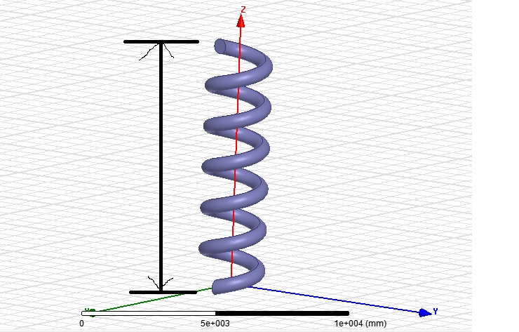
Capacitance, inductance and coil designing in Q3D.

Hi, I am trying to design a capacitor, inductor and a coil in Q3d software but could not find any clues. Can any one help me. Thank you in advance.
 

You may start with copper metal trace (create rectangle), and then forming into spiral geometry if you want a spiral inductor. The two ends will serve as your two ports.
 

Hello, tanq very much for your suggestion. I have created a coil how can I measure it now, actually my intention is to measure the inductance of the two ends by arrows. Please look at the coil I have created in the image.

https://obrazki.elektroda.pl/3403146200_1389623960.jpg

Thank you in advance.
 

Hi Shera,

Specify first the correct material for your coil, or is it already copper?
Then select the coil and assign net (signal) on it.
 

Hello fredd,
yes it is a copper material and I have got the results. Thank you for your help. Can you suggest me how can we change the frequency???
 

Hi Shera,

Have you done the "Add Solution Setup" under Analysis?
You can change the solution frequency then.
 

Hi Fredd,
thank you for that. I have a small doubt. How can we measure inductance of the coil ???? I need to measure at the two ends of the coil as shown in the picture. Can you suggest me how to do that in q3d software.

Link for the image is below please have a look.

https://obrazki.elektroda.pl/3257137100_1389868796.jpg


Hello Shera,

You can assign the two ends (two faces) as the ports.
You can refer to the manual for the assignment of ports using faces.
 
  • Like
Reactions: shera

    shera

    Points: 2
    Helpful Answer Positive Rating
Status
Not open for further replies.

Part and Inventory Search

Welcome to EDABoard.com

Sponsor

Back
Top