Superdude_123
Newbie level 4
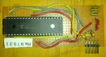
As per the attached picture, I've built Fig 10-2 on P21 of **broken link removed**, and I can't seem to make it work. I've presently joined the 10K resistor and the yellow wire that leads to MCLR with alligator cable (not shown) together (to complete the circuit). Every time I try to program my 16F877a chip with my MikroProg programmer, I always get a Vpp voltage error as being too low (~9 V when its expecting 12 V). My question is, why is it that after building the circuit as shown in the figure, does it still not work?
I've traced all the 2x5 male header pins to the DIP pins, and everything tested perfect (skipped the caps). I'm using ceramic capacitors (4x 47.3 nF).
Could it be possible that my PIC chip is dead or damaged from static electricity? I have doubts that my programmer is bad, but this is really my 2nd try with it.