Continue to Site

Welcome to EDAboard.com

Welcome to our site! EDAboard.com is an international Electronics Discussion Forum focused on EDA software, circuits, schematics, books, theory, papers, asic, pld, 8051, DSP, Network, RF, Analog Design, PCB, Service Manuals... and a whole lot more! To participate you need to register. Registration is free. Click here to register now.

can't get BJT in saturation mode while charging battery

Status
Not open for further replies.

Nik_Henri

Newbie level 4
Joined
Nov 22, 2011
Messages
5
Helped
0
Reputation
0
Reaction score
0
Trophy points
1,281
Activity points
1,320
Hi,
I would like to be able to charge a battery pack (12v 6A/h) from a power supply. I can charge it directly if i connect the battery on the power supply but i would like to have switch so i can stop the charge but my MCU. I try to make a very simple circuit that would act has a ON/OFF switch but i cant get my PNP work in saturation so the current is 600ma (expecting about 2A) and the VCE is 11V (expecting about 0.2v). What am I doing wrong ?

here's the circuit
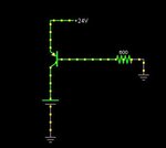
siml.JPG

thx for the help
 

What type of battery is it? If you try to put 24V directly on to a 12V battery then there is likely to be a large bang unless you have something to limit the current. At the moment it seems like the transistor is doing that job. What transistor are you using?

Keith.
 

I use a 12v 6A/h NIMH battery pack
I dont have to worry about the current because it's limited by my voltage source at 2A

The battery take the 2A when directly connected to the voltage source but not when i put the BJT

---------- Post added at 16:46 ---------- Previous post was at 16:18 ----------

transtor is a TIP32C
 

From appearances your setup should work. You are giving the emitter a direct path to V+. You are biasing the PNP to ground. This gives maximum sensitivity. The bias can be as small as 0.6 V E-B and you should get flow into the battery.

A battery does odd things in a circuit. It can cause unexpected volt levels to appear at nodes. It can't be simulated by a capacitor because a capacitor has very high resistance unlike a battery.

However what is your charging device? You say it's current limited. Is it the kind that shuts off unless it detects a sufficiently low load resistance, and then it turns on?

The 600 ohm bias resistor is the only load, at the start. Is that able to turn on the charging device?
 

If you 24V drops due to the current limit then you are probably only putting 20mA into the transistor base. The transistor current gain is probably only 30 so you will only get 600mA of collector current. You need to reduce your base resistor. Then you will need to add an extra transistor because the microcontroller will not be able to drive the base current.

Keith
 

You will need an extra transistor anyway to interface to a micro -most micros will not tolerate the 24V on the I/O pin when the output is turned off.
 

Status
Not open for further replies.

Similar threads

Part and Inventory Search

Welcome to EDABoard.com

Sponsor

Back
Top